Reduced Safety/Reliability: Arc Flash Hazard Example
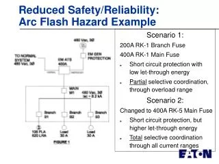
This document explores two scenarios regarding arc flash hazards in electrical systems, specifically focusing on different main fuses (200A RK-1 vs. 400A RK-5) and their impact on short circuit protection and let-through energy. Scenario 1 illustrates the advantages of a 200A RK-1 branch fuse with lower let-through energy and partial selective coordination. In contrast, Scenario 2, using a 400A RK-5 main fuse, provides higher let-through energy but achieves total selective coordination across all current ranges. Key safety and reliability considerations are examined alongside IEEE 1584 calculated incident energy.

Reduced Safety/Reliability: Arc Flash Hazard Example
E N D
Presentation Transcript
Reduced Safety/Reliability: Arc Flash Hazard Example Scenario 1: 200A RK-1 Branch Fuse 400A RK-1 Main Fuse • Short circuit protection with low let-through energy • Partial selective coordination, through overload range Scenario 2: Changed to 400A RK-5 Main Fuse • Short circuit protection, but higher let-through energy • Total selective coordination through all current ranges
Reduced Safety/Reliability: Arc Flash Hazard Example (cont’d) Description AvailableFault Current 8200A 8200A 8200A IEEE 1584 CalculatedIncident Energy, Cal/cm2 0.7 8.4 0.4 Category PPERequired 0 3 0 Scenario 1 Scenario 2 NEC Mandated Scenario 3 (For comparison purposes) PARTIAL Selective Coordination 400 Ampere Molded Case Main Circuit Breaker PARTIAL Selective Coordination 400 Ampere Class RK 1 Main Fuse TOTAL Selective Coordination 400 Ampere Class RK 5 Main Fuse