Download
1 / 44
440 likes | 679 Vues
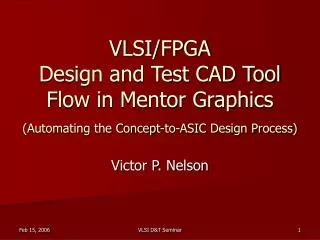
VLSI/FPGA Design and Test CAD Tool Flow in Mentor Graphics (Automating the Concept-to-ASIC Design Process). Victor P. Nelson. Mentor Graphics CAD Tool Suites. IC/SoC design flow 1 DFT/BIST/ATPG design flow 1 FPGA design flow 2 PCB design flow 2

E N D
VLSI/FPGADesign and Test CAD Tool Flow in Mentor Graphics(Automating the Concept-to-ASIC Design Process) Victor P. Nelson VLSI D&T Seminar
Mentor Graphics CAD Tool Suites • IC/SoC design flow1 • DFT/BIST/ATPG design flow1 • FPGA design flow2 • PCB design flow2 • Digital/analog/mixed-signal modeling & simulation1,2 • ASIC/FPGA synthesis1,2 • Vendor-provided (Xilinx,Altera,etc.) back end tools2 • User-setup selection: eda/mentor/ICFlow2004.3 • User-setup selection: eda/mentor/EN2002.3 VLSI D&T Seminar
Mentor Graphics CAD Tools (select “eda/mentor” in user-setup on the Sun network*) • ICFlow2004.3(2001, 2005.1) – For custom & standard cell IC designs • IC flow tools(Design Architect-IC, IC Station, Calibre) • Digital/analog/mixed simulation (Modelsim,ADVance MS,Eldo,MachTA) • HDL Synthesis(Leonardo) • ATPG/DFT/BIST tools (DFT Advisor, Flextest, Fastscan) • Limited access to Quicksim II (some technologies) • EN2002u3(EN2001) – For FPGA “front end” design & printed circuit boards • Design Architect, Quicksim II, Quicksim Pro (Schematic/Simulation) • ModelSim & Leonardo (HDL Simulation/Synthesis) • Xilinx ISE & Altera “Quartus” tools (Back end design) • FPGA(FPGA Advantage, Modelsim, Leonardo) *Only one of the above three groups may be selected at a time VLSI D&T Seminar
Mentor Graphics ASIC Design Kit (ADK) • Technology files & standard cell libraries • AMI: ami12, ami05 (1.2, 0.5 μm) • TSMC: tsmc035, tsmc025, tsmc018* (0.35, 0.25, 0.18 μm) * No std. cells for tsmc018 • IC flow & DFT tool support files: • Simulation • VHDL/Verilog/Mixed-Signal models(Modelsim/ADVance MS) • Analog (SPICE) models(Eldo/Accusim) • Post-layout timing (Mach TA) • Digital schematic (Quicksim II, Quicksim Pro)(exc. tsmc025,tsmc018) • Synthesis to std. cells (LeonardoSpectrum) • Design for test & ATPG (DFT Advisor, Flextest/Fastscan) • Schematic capture (Design Architect-IC) • IC physical design (standard cell & custom) • Floorplan, place & route (IC Station) • Design rule check, layout vs schematic, parameter extraction (Calibre) VLSI D&T Seminar
Xilinx/Altera FPGA/CPLD Design • Technology files & libraries for front-end design with Mentor Graphics tools • Schematic symbols for Design Architect • Simulation models forQuicksim II, Quicksim Pro • Synthesis library for Leonardo • Vendor tools for back-end design (map, place, route, configure, timing) • Xilinx Integrated Software Environment (ISE) • Altera Quartus II & Max+Plus2 VLSI D&T Seminar
ASIC Design Flow Behavioral Model VHDL/Verilog Verify Function Synthesis DFT/BIST & ATPG Gate-Level Netlist Verify Function Full-custom IC Test vectors Transistor-Level Netlist Verify Function & Timing Standard Cell IC & FPGA/CPLD DRC & LVS Verification Physical Layout Map/Place/Route Verify Timing VLSI D&T Seminar IC Mask Data/FPGA Configuration File
Digital/Mixed-Signal Simulation VHDL,Verilog, VHDL-AMS, Verilog-A, SPICE Models VITAL Resource Libraries Design_1 Design_2 IEEE 1164 Working Library ADVance MS Input Stimuli Simulation Setup Mixed Signal (VHDL-AMS, Verilog-A) EZwave or Xelga Eldo, Eldo RF ModelSim Analog (SPICE) Mach TA View Results Digital (VHDL,Verilog) VLSI D&T Seminar
Example: 4-bit binary counter • VHDL model(count4.vhd) • Create working library: vlib work vmap work work • Compile: vcom count4.vhd • Simulate: vsim count4(rtl) • ModelSim simulation-control inputs • ModelSim “Macro” (count4_rtl.do) • OR, VHDL testbench • ModelSim results • listing or waveform VLSI D&T Seminar
-- count4.vhd 4-bit parallel-load synchronous counter LIBRARY ieee; USE ieee.std_logic_1164.all; USE ieee.numeric_std.all; ENTITY count4 IS PORT (clock,clear,enable,load_count : IN STD_LOGIC; D: IN unsigned(3 downto 0); Q: OUT unsigned(3 downto 0)); END count4; ARCHITECTURE rtl OF count4 IS SIGNAL int : unsigned(3 downto 0); BEGIN PROCESS(clear, clock, enable) BEGIN IF (clear = '1') THEN int <= "0000"; ELSIF (clock'EVENT AND clock='1') THEN IF (enable = '1') THEN IF (load_count = '1') THEN int <= D; ELSE int <= int + "01"; END IF; END IF; END IF; END PROCESS; Q <= int; END rtl; VLSI D&T Seminar
Modelsim “do” file: count4_rtl.do add wave /clock /clear /enable /load_count /D /Q add list /clock /clear /enable /load_count /D /Q force /clock 0 0, 1 10 -repeat 20 force /clear 0 0, 1 5, 0 10 force /enable 0 0, 1 25 force /load_count 0 0, 1 20, 0 35, 1 330, 0 350 force /D 10#5 0, 10#9 300 run 400 VLSI D&T Seminar
Count4 – Simulation waveform Clear Counting Parallel Load VLSI D&T Seminar
Automated Synthesis with Leonardo Spectrum VHDL/Verilog Behavioral/RTL Models Technology Synthesis Libraries FPGA Leonardo Spectrum (Level 3) Design Constraints ASIC ADK AMI 0.5, 1.2 TSMC 0.35, 0.25 Level 1 – FPGA Level 2 – FPGA + Timing Technology- Specific Netlist VHDL, Verilog, SDF, EDIF, XNF VLSI D&T Seminar
Synthesis in Leonardo:HDL to technology-specific netlist • Invoke leonardo • Select & load a technology library (ASIC or FPGA) • ASIC > ADK > TSMC 0.35 micron • Read input VHDL/Verilog file(s): count4.vhd • Enter any constraints (clock freq, delays, etc.) • Optimize for area/delay/effort level • Write output file(s) • count4_0.vhd - VHDL netlist • count4.v - Verilog netlist (for IC layout) • count4.sdf - Standard delay format file (for timing) • count4.edf - EDIF netlist (for Xilinx/Altera FPGA) VLSI D&T Seminar
Leonardo-synthesized netlist count4_0.vhd library IEEE; use IEEE.STD_LOGIC_1164.all; library adk; use adk.adk_components.all; -- ADDED BY VPN entity count4 is port ( clock : IN std_logic ; clear : IN std_logic ; enable : IN std_logic ; load_count : IN std_logic ; D : IN std_logic_vector (3 DOWNTO 0) ; Q : OUT std_logic_vector (3 DOWNTO 0)) ; end count4 ; architecture netlist of count4 is -- rtl changed to netlist by VPN signal Q_3_EXMPLR, Q_2_EXMPLR, Q_1_EXMPLR, Q_0_EXMPLR, nx8, nx14, nx22, nx28, nx48, nx54, nx62, nx126, nx136, nx146, nx156, nx169, nx181, nx183, nx185, nx187, nx189: std_logic ; begin Q(3) <= Q_3_EXMPLR ; Q(2) <= Q_2_EXMPLR ; Q(1) <= Q_1_EXMPLR ; Q(0) <= Q_0_EXMPLR ; Q_0_EXMPLR_EXMPLR : dffr port map ( Q=>Q_0_EXMPLR, QB=>OPEN, D=>nx126, CLK=>clock, R=>clear); ix127 : mux21_ni port map ( Y=>nx126, A0=>Q_0_EXMPLR, A1=>nx8, S0=>enable ); ix9 : oai21 port map ( Y=>nx8, A0=>load_count, A1=>Q_0_EXMPLR, B0=>nx169 ); ix170 : nand02 port map ( Y=>nx169, A0=>D(0), A1=>load_count); Q_1_EXMPLR_EXMPLR : dffr port map ( Q=>Q_1_EXMPLR, QB=>OPEN, D=>nx136, CLK=>clock, R=>clear); ix137 : mux21_ni port map ( Y=>nx136, A0=>Q_1_EXMPLR, A1=>nx28, S0=> enable); ix29 : ao22 port map ( Y=>nx28, A0=>D(1), A1=>load_count, B0=>nx14, B1=> nx22); ix15 : or02 port map ( Y=>nx14, A0=>Q_0_EXMPLR, A1=>Q_1_EXMPLR); ix23 : aoi21 port map ( Y=>nx22, A0=>Q_1_EXMPLR, A1=>Q_0_EXMPLR, B0=> load_count); Q_2_EXMPLR_EXMPLR : dffr port map ( Q=>Q_2_EXMPLR, QB=>OPEN, D=>nx146, CLK=>clock, R=>clear); ix147 : mux21_ni port map ( Y=>nx146, A0=>Q_2_EXMPLR, A1=>nx48, S0=> enable); ix49 : oai21 port map ( Y=>nx48, A0=>nx181, A1=>nx183, B0=>nx189); ix182 : aoi21 port map ( Y=>nx181, A0=>Q_1_EXMPLR, A1=>Q_0_EXMPLR, B0=> Q_2_EXMPLR); ix184 : nand02 port map ( Y=>nx183, A0=>nx185, A1=>nx187); ix186 : inv01 port map ( Y=>nx185, A=>load_count); ix188 : nand03 port map ( Y=>nx187, A0=>Q_2_EXMPLR, A1=>Q_1_EXMPLR, A2=> Q_0_EXMPLR); ix190 : nand02 port map ( Y=>nx189, A0=>D(2), A1=>load_count); Q_3_EXMPLR_EXMPLR : dffr port map ( Q=>Q_3_EXMPLR, QB=>OPEN, D=>nx156, CLK=>clock, R=>clear); ix157 : mux21_ni port map ( Y=>nx156, A0=>Q_3_EXMPLR, A1=>nx62, S0=> enable); ix63 : mux21_ni port map ( Y=>nx62, A0=>nx54, A1=>D(3), S0=>load_count); ix55 : xnor2 port map ( Y=>nx54, A0=>Q_3_EXMPLR, A1=>nx187); end netlist ; VLSI D&T Seminar
// Verilog description for cell count4, LeonardoSpectrum Level 3, 2005a.82 module count4 ( clock, clear, enable, load_count, D, Q ) ; input clock ; input clear ; input enable ; input load_count ; input [3:0]D ; output [3:0]Q ; wire nx8, nx14, nx22, nx28, nx48, nx54, nx62, nx126, nx136, nx146, nx156, nx169, nx181, nx183, nx185, nx187, nx189; wire [3:0] \$dummy ; dffr Q_0__rename_rename (.Q (Q[0]), .QB (\$dummy [0]), .D (nx126), .CLK (clock), .R (clear)) ; mux21_ni ix127 (.Y (nx126), .A0 (Q[0]), .A1 (nx8), .S0 (enable)) ; oai21 ix9 (.Y (nx8), .A0 (load_count), .A1 (Q[0]), .B0 (nx169)) ; nand02 ix170 (.Y (nx169), .A0 (D[0]), .A1 (load_count)) ; dffr Q_1__rename_rename (.Q (Q[1]), .QB (\$dummy [1]), .D (nx136), .CLK (clock), .R (clear)) ; mux21_ni ix137 (.Y (nx136), .A0 (Q[1]), .A1 (nx28), .S0 (enable)) ; ao22 ix29 (.Y (nx28), .A0 (D[1]), .A1 (load_count), .B0 (nx14), .B1 (nx22) ) ; or02 ix15 (.Y (nx14), .A0 (Q[0]), .A1 (Q[1])) ; aoi21 ix23 (.Y (nx22), .A0 (Q[1]), .A1 (Q[0]), .B0 (load_count)) ; dffr Q_2__rename_rename (.Q (Q[2]), .QB (\$dummy [2]), .D (nx146), .CLK (clock), .R (clear)) ; mux21_ni ix147 (.Y (nx146), .A0 (Q[2]), .A1 (nx48), .S0 (enable)) ; oai21 ix49 (.Y (nx48), .A0 (nx181), .A1 (nx183), .B0 (nx189)) ; aoi21 ix182 (.Y (nx181), .A0 (Q[1]), .A1 (Q[0]), .B0 (Q[2])) ; nand02 ix184 (.Y (nx183), .A0 (nx185), .A1 (nx187)) ; inv01 ix186 (.Y (nx185), .A (load_count)) ; nand03 ix188 (.Y (nx187), .A0 (Q[2]), .A1 (Q[1]), .A2 (Q[0])) ; nand02 ix190 (.Y (nx189), .A0 (D[2]), .A1 (load_count)) ; dffr Q_3__rename_rename (.Q (Q[3]), .QB (\$dummy [3]), .D (nx156), .CLK (clock), .R (clear)) ; mux21_ni ix157 (.Y (nx156), .A0 (Q[3]), .A1 (nx62), .S0 (enable)) ; mux21_ni ix63 (.Y (nx62), .A0 (nx54), .A1 (D[3]), .S0 (load_count)) ; xnor2 ix55 (.Y (nx54), .A0 (Q[3]), .A1 (nx187)) ; endmodule VLSI D&T Seminar
Post-synthesis simulation(with Leonardo-generated netlist) • Verify synthesized netlist vs behavioral model • Create simulation primitives library for std cells: >vlib adk >vcom $ADK/technology/adk.vhd >vcom $ADK/technology/adk_comp.vhd • Insert library/package declaration in netlist library adk; use adk.adk_components.all; • Simulate in Modelsim, using “do file” from behavioral simulation – results should be same VLSI D&T Seminar
Design for Test & Test Generation Memory & Logic BIST Boundary Scan Internal Scan Design ATPG VLSI D&T Seminar
DFTadvisor/FastScan Design Flow count4.vhd count4_0.vhd count4.v DFT/ATPG Library: adk.atpg count4_scan.v VLSI D&T Seminar Source: FlexTest Manual
Example DFTadvisor session • Invoke: • dftadvisor –verilog count4.v –lib $ADK/technology/adk.atpg • Implement scan with defaults: (full scan, mux-DFF scan elements) • set system mode setup • analyze control signals –auto • set system mode dft • run • insert test logic • write netlist count4_scan.v –verilog • write atpg setup count4_scan (creates count4_scan.dofile for ATPG in Fastscan) VLSI D&T Seminar
count4 – without scan design VLSI D&T Seminar
count4 – scan inserted by DFTadvisor VLSI D&T Seminar
ATPG with FastScan (full-scan circuit) • Invoke: • fastscan –verilog count4.v –lib $ADK/technology/adk.atpg • Generate test pattern file: • dofile count4_scan.dofile (defines scan path & procedure) • set system mode atpg • create patterns –auto (generate test patterns) • save patterns Note: “count4_scan.dofile” created by DFTadvisor VLSI D&T Seminar
scan_group "grp1" = scan_chain "chain1" = scan_in = "/scan_in1"; scan_out = "/output[3]"; length = 4; end; procedure shift "grp1_load_shift" = force_sci "chain1" 0; force "/clock" 1 20; force "/clock" 0 30; period 40; end; procedure shift "grp1_unload_shift" = measure_sco "chain1" 10; force "/clock" 1 20; force "/clock" 0 30; period 40; end; procedure load "grp1_load" = force "/clear" 0 0; force "/clock" 0 0; force "/scan_en" 1 0; apply "grp1_load_shift" 4 40; end; procedure unload "grp1_unload" = force "/clear" 0 0; force "/clock" 0 0; force "/scan_en" 1 0; apply "grp1_unload_shift" 4 40; end; end; Test file: scan chain definition and load/unload procedures VLSI D&T Seminar
Generated scan-based test // send a pattern through the scan chain CHAIN_TEST = pattern = 0; apply "grp1_load" 0 = (use grp1_load procedure) chain "chain1" = "0011"; (pattern to scan in) end; apply "grp1_unload" 1 = (use grp1_unload procedure) chain "chain1" = "1100"; (pattern scanned out) end; end; // one of 14 patterns for the counter circuit pattern = 0; (pattern #) apply "grp1_load" 0 = (load scan chain) chain "chain1" = "1000"; (scan-in pattern) end; force "PI" "00110" 1; (PI pattern) measure "PO" "0010" 2; (expected POs) pulse "/clock" 3; (normal op. cycle) apply "grp1_unload" 4 = (read scan chain) chain "chain1" = "0110"; (expected pattern) end; VLSI D&T Seminar
ASIC Physical Design (Standard Cell) Component-Level Netlist (EDDM format) Std. Cell Layouts Mentor Graphics “IC Station” (adk_ic) Floorplan Chip/Block Libraries ICblocks Process Data Place & Route Std. Cells Design Rules Generate Mask Data Design Rule Check Backannotate Schematic Layout vs. Schematic Check Calibre Calibre Calibre VLSI D&T Seminar IC Mask Data Mach TA/Eldo Simulation Model
Preparation for Layout • Use Design Architect-IC to convert Verilog netlist to Mentor Graphics “EDDM” schematic/netlist format • Invoke Design Architect-IC (adk_daic) • On menu bar, select File > Import Verilog • Netlist file: count4.v (the Verilog netlist) • Output directory: count4(for the EDDM netlist) • Mapping file $ADK/technology/adk_map.vmp • Open the generated schematic for viewing • Click Schematic in DA-IC palette • Select schematic in directory named above (see next slide) • Click Update LVS in the schematic palette to create a netlist to be used later by “Calibre” • Create design viewpoints for ICstation tools • adk_dve count4 –t tsmc035 (V.P’s: layout, lvs, sdl, tsmc035) • Can also create gate/transistor schematics directly in DA-IC using components from the ADK library VLSI D&T Seminar
DA-IC generated schematic VLSI D&T Seminar
Create a std-cell based logic block in IC Station • Invoke: adk_ic • In IC Station palette, select:Create Cell • Cell name: count4 • Attach library: $ADK/technology/ic/process/tsmc035 • Process: $ADK/technology/ic/process/tsmc035 • Rules file: $ADK/technology/ic/process/tsmc035.rules • Angle mode: 45 • Cell type: block • Select With connectivity • EDDM schematic viewpoint:count4/layout • Logic loading options: flat VLSI D&T Seminar
Create Cell dialog box VLSI D&T Seminar
Cell-Based IC VLSI D&T Seminar
Cell-Based Block VLSI D&T Seminar
Basic standard Cell layout VLSI D&T Seminar Source: Weste “CMOS VLSI Design”
Auto “floorplan” the blockplace & route > autofp VLSI D&T Seminar
Auto-place the std cellsAutoplc > StdCel VLSI D&T Seminar
Auto-place “ports” (Autoplc > Ports)Signal connections on cell boundaries VLSI D&T Seminar
AutoRoute all nets(hand-route any unrouted “overflows”) VLSI D&T Seminar Then: Add > Port Text to copy port names from schematic – for Calibre
Layout design rule check (DRC) • Technology-specific design rules specify minimum sizes, spacing, etc. of features to ensure reliable fabrication • Design rules file specified at startup Ex. tsmc035.rules • From main palette, select ICrules • Click Check and then OK in prompt box (can optionally select a specific area to check) • Rules checked in numeric order VLSI D&T Seminar
Common errors detected by DRC • To fix, click on First in palette to highlight first error • Error is highlighted in the layout • Click View to zoom in to the error (see next) • Example: DRC9_2: Metal2 spacing = 3L • Fix by drawing a rectangle of metal2 to fill in the gap between contacts that should be connected • Click Next to go to next error, until all are fixed NOTE: There must be no DRC errors if MOSIS is to fabricate the chip – they will run their own DRC. VLSI D&T Seminar
Error: DRC9_2 metal2 spacing = 3L Draw rectangle of metal2 to fill gap VLSI D&T Seminar It also called contact-to-contact metal 2 spacing DRC9_2 error
Layout vs schematic checkCalibre Interactive LVS • From ICstation menu: Calibre > Run LVS • In popup, Calibre location: $MGC_HOME/../Calibre • Rules: $ADK/technology/ic/process/tsmc035.calibre.rules • Input: count4.src.net (previously created in DA-IC) • H-cells: $ADK/technology/adk.hcell (hierarchical cells) • Extracted file: count4.lay.net • Compares extracted transistor-level netlist vs. netlist saved in DA-IC VLSI D&T Seminar
Post-layout parameter extractionCalibre Interactive PEX • Extract Spice netlist, including parasitic RC • Simulate in Eldo or MachTA • ICstation menu: Calibre>Run PEX • Options similar to Calibre LVS • Extraction options: • lumped C + coupling cap’s • distributed RC • distributed RC + coupling cap’s • Output file: count4.pex.netlist VLSI D&T Seminar
Post-layout simulation with MachTA • MachTA is an accelerated Spice simulator • Can do standard Spice analyses (dc transient) • Can execute a test vector file • Results displayed in “EZwave” • Prepare netlist for MachTA (remove subcircuits) • mta_prep count4 • Invoke: mta –ezw –t $ADK/technology/mta/tsmc035 TYP count4.sp VLSI D&T Seminar
Physical Design - FPGA Component-Level Netlist Xilinx “ISE” Altera “Max Plus 2” Map to FPGA LUTs, FFs, IOBs FPGA/PLD Technology Files Place & Route User-Specified Constraints Generate Programming Data Generate Timing Model VLSI D&T Seminar Configuration File Simulation Model
ADVance MS Simulation System • ADVance MS “kernel” supports: • VHDL & Verilog: digital (via ModelSim) • VHDL-AMS & Verilog-A: analog/mixed signal • Eldo/SPICE: analog (via Eldo) • Eldo RF/SPICE: analog RF (via Eldo RF) • Mach TA/SPICE: high-speed analog/timing • Invoke stand-alone or from Design Architect-IC • Mentor Graphics “Legacy” Simulators (PCB design) • Quicksim II, Quicksim Pro (digital) • ASIC: adk_quicksim • FPGA/PLD: Xilinx: pld_quicksim, Altera: max2_quicksim • Accusim (analog): adk_accusim VLSI D&T Seminar