Evolution of All-Aluminum Heater Cores: Market Trends and Technological Advancements
Explore the market trends and technological advancements in all-aluminum heater cores since 1990, with a focus on high performance, compactness, and mechanical resistance. Learn about the all-aluminum brazed technology, optimized heat exchange architecture, and standardization efforts driving evolution in heater cores.

Evolution of All-Aluminum Heater Cores: Market Trends and Technological Advancements
E N D
Presentation Transcript
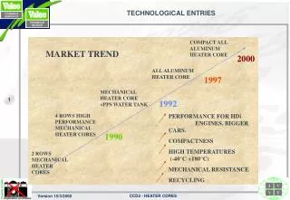
COMPACT ALL ALUMINUM HEATER CORE MARKET TREND 2000 ALL ALUMINUM HEATER CORE 1997 MECHANICAL HEATER CORE +PPS WATER TANK 1992 4 ROWS HIGH PERFORMANCE MECHANICAL HEATER CORES PERFORMANCE FOR HDi ENGINES, BIGGER CARS. COMPACTNESS HIGH TEMPERATURES (-40°C +180°C) MECHANICAL RESISTANCE RECYCLING 1990 2 ROWS MECHANICAL HEATER CORES TECHNOLOGICAL ENTRIES
CORE COMPOSITION Water tank Sleeves Stamped Stamped Tubes Bended and Stamped Baffle Cutted and stamped End plates Cutted and Header stamped Stamped Flat tubes Stamped Fins Forming tool End caps Stamped
CIRCUITING ALL ALUMINUM BRAZED HEATER CORE Heat transfer in the tubes and not in the tank gain in performance Air flow Set up of laminary boundary layer U -flow Cross - counter flow tube with design with design integrated return tank water return
Implantation in housing recommendations 1/2 Heater cores position Proximity between electric or electronique components and heater core hot zones should be studied during implantation To avoid contact between passenger and heater core. To be sure that no condensation projection from evaporator on the heater core create particular odor . The better implantation is described on the following sketch (to avoid degazing problem). Vehicle Liquid oulet Z Axis AIR Liquid inlet
Implantation in housing recommendations 2/2 From NVF 10010 specification Heater core header screwed on housing Red colour Housing Two ribs to maintain Heater core in housing Housing form to block Heater core in housing
CONCLUSIONS HEATER CORE EVOLUTION GOES TO: • Stronger mechanical strength • Increase of performance • Compactness • Standardisation • Cost reductions This evolution was made possible thanks to the all aluminium brazed technology. • Heat exchange architecture is optimised thanks to flat tube patented design • This technology, as plate fins evaporator technology, eases heater core standardisation ; • Branch know how includes a well controlled process able to reach large volumes.