Telecommunications Chapter 6
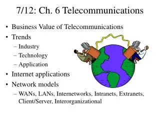
Telecommunications Chapter 6. Telecommunications. From Chapter 1: Data communications Telecommunications: Voice and Video Communications. Technical Elements of the Public Switched Telephone Network. Figure 6-1: Elements of the Public Switched Telephone Network (PSTN). 1. Customer Premises

Telecommunications Chapter 6
E N D
Presentation Transcript
Telecommunications • From Chapter 1: • Data communications • Telecommunications: Voice and Video Communications
Figure 6-1: Elements of the Public Switched Telephone Network (PSTN) 1. Customer Premises Equipment 1. Customer Premises Equipment
Figure 6-2: Customer Premises Equipment A typical business site. The private branch exchange is an internal switch for the site. 4-pair UTP was created for business premises telephone wiring Company is essentially its own telephone company that connects to the outside PSTN
Figure 6-1: Elements of the Public Switched Telephone Network (PSTN) The Access System consists of the access line to the customer(called the local loop) and termination equipment at the end office(nearest telephone office switch). 2. Access Line (Local Loop) 2. Access Line (Local Loop) 2. & 3. End Office Switch (Class 5)
Figure 6-1: Elements of the Public Switched Telephone Network (PSTN) 3. Transport Core 3. Switch 3. Trunk Line The Transport Core connects end office switches and core switches. Trunk lines connect switches.
Figure 6-1: Elements of the PSTN • Telephone Company Switch
Figure 6-1: Elements of the Public Switched Telephone Network (PSTN) 4. Signaling System Transport is the actual transmission of voice. Signaling is the control of calling(setup, teardown, billing, etc.). SS7 in the United States C7 in Europe
Figure 6-3: Points of Presence (POPs) In the U.S., competing carriers connect at points of presence (POPs).
Figure 6-5: Voice and Data Traffic The reserved capacity of circuit switching is OK for voice, but not for bursty data transmission.
Figure 6-6: Dial-Up Circuits Versus Leased Line Circuits Dial-Up Circuits Leased Line Circuits Operation Dial-Up. Separate circuit for each call. Permanent circuit, always on. Speed for Carrying Data Up to 56 kbps Residence can only Send up to 33.6 kbps 56 kbps to gigabit speeds Number of Voice Calls Multiplexed One Several due to multiplexing There are two types of circuits between customer premises: ordinary dial-up circuits and leased line circuits.
Figure 6-7: Local Loop Technologies Technology Use Status 1-Pair Voice-Grade UTP Residences Already installed 2-Pair Data-Grade UTP Businesses for Lowest-speed access lines Must be pulled to the customer premises (this is expensive) Optical Fiber Businesses for higher-speedaccess lines Must be pulled to the customer premises (this is expensive) Residential 1-pair voice-grade UTP is already installed.This makes it inexpensive to use Business 2-pair data-grade UTP and fiber for leased lines must be installed; this is expensive.
Figure 6-8: Analog Telephone Transmission Analog signals rise and fall in intensity with the human voice. No resistance to errors as there is in digital transmission. Initially, the entire PSTN was analog.
Figure 6-9: The PSTN: Mostly Digital with Analog Local Loops Today, everything is digital except for the local loop access line and residential telephones. The actual local loop line can carry either analog or digital signals, but the equipment at both ends is analog.
Figure 6-10: Codec at the End Office Switch A codec at the end office translates between residential analog and PSTN digital signaling. ADC = analog to digital conversion DAC = digital to analog conversion
Figure 6-11: Frequency Division Multiplexing (FDM) in Microwave Transmission Box: Codec Operation Microwave uses radio transmission for PSTN trunk lines
Figure 6-12: Analog-to-Digital Conversion (ADC): Bandpass Filtering and Pulse Code Modulation (PCM) Box: Codec Operation Filter at End Office Switch At the end office, the voice signal is bandpass-filtered to limit its bandwidth to 4 MHz. This permits more calls to be multiplexed on trunk lines
Figure 6-12: Analog-to-Digital Conversion (ADC): Bandpass Filtering and Pulse Code Modulation (PCM) Box: Codec Operation Actually, to provide a safety margin, the signal is filtered to between about 300 Hz and 3.4 kHz instead of from 0 Hz to 4 kHz.
Figure 6-12: Analog-to-Digital Conversion (ADC): Bandpass Filtering and Pulse Code Modulation (PCM) Box: Codec Operation Nyquist found that signals must be sampled at twice their highest frequency. For a top frequency of 4 kHz, there must be 8,000 samples per second. Each sample is 1/8000 second.
Figure 6-12: Analog-to-Digital Conversion (ADC): Bandpass Filtering and Pulse Code Modulation (PCM) In each sampling period, the intensity of the signal is measured. In pulse code modulation, the signal is measured as one of 256 intensity levels. One byte stores one sample. Box: Codec Operation
Figure 6-12: Analog-to-Digital Conversion (ADC): Bandpass Filtering and Pulse Code Modulation (PCM) Pulse Code Modulation (PCM) produces 8,000 one-byte samples per second. This is 64 kbps of data. Box: Codec Operation
Box: Codec Operation ADC Recap • First, Bandpass-Filter the Incoming Signal to 4 kHz • Really about 300 Hz to 3.4 kHz • To reduce transmission requirements • The Codec then Uses PCM for the Conversion • Samples at twice the highest frequency (4 kHz so 8,000 samples/second) • Loudness is recorded with 8 bits per sample (to give 256 loudness levels) • Generates 64 kbps of traffic (8 bits/sample times 8,000 samples per second)
Figure 6-13: Digital-to-Analog Conversion (DAC) Box: Codec Operation One 8-Bit Sample One 8-Bit Sample 00000100 00000011 00000111 To Customer: Generated “analog” signal (Sounds smooth because the sampling rate is very high) From digital PSTN network: Arriving digital signal from the PSTN Core (8,000 Samples/Second) DAC at End Office Switch
Figure 6-14: Cellular Telephony In cellular technology, the region is divided into smaller cells. In each cell, a cellsite serves cellphones in the cell.
Figure 6-14: Cellular Telephony • Cellsites
Figure 6-14: Cellular Telephony Channels can be reused in different cells. Channel reuse supports more customers. This is the reason for using cells. (Channel 47 is reused in cells A, D, and F)
Figure 6-14: Cellular Telephony When a subscriber moves from one cell to another in a cellular system, this is called a handoff. When a subscriber moves from one city to another, this is roaming. (In WLANs, handoffs and roaming mean the same thing.)
Figure 6-14: Cellular Telephony The Mobile Telephone Switching Office (MTSO) coordinates the cellsites and implements signaling and handoffs. The MTSO also connects cellphones to the PSTN (called the wireline network).
Cellular Technologies • GSM is the worldwide standard for cellular voice • Uses time division multiplexing (TDM) • Uses 200 kHz channels • Divides each second into many frame periods • Divides each frame into 8 slots • Gives same slot in each frame to a conversation Time Frame 1 Frame 2 Slot 1 Conversation A Slot 2 Conversation B Slot 8 Conversation H Slot 1 Conversation A ……
Cellular Technologies • Cannot use the same channel in adjacent cells • So can only reuse a channel about every 7 cells • For example, suppose there are 50 cells • Channel can be reused 50 / 7 times • This is 7 (not precise, so round things off) • So each channel can support 7 simultaneous customers in these 7 cells
Cellular Technologies • Code Division Multiple Access (CDMA) • Also used in the United States • A form of spread spectrum transmission • Unlike traditional spread spectrum technology, multiple users can transmit simultaneously • 1.25 MHz channels • Can support many users per channel • Can use the same channel in adjacent cells • So can only reuse a channel in every cell
Figure 6-15: Voice over IP (VoIP) VoIP carries telephone calls over LANs and the Internet With IP, there is no wasted capacity as there is with circuit switching. This reduces cost.
Figure 6-15: Voice over IP (VoIP) Stations can be special IP telephones with IP functionality Or a PC with multimedia hardware and VoIP software IP phones need a codec to convert voice analog signals from the microphone into digital IP signals
Figure 6-15: Voice over IP (VoIP) A media gateway connects a VoIP network to the PSTN Handles transport and signaling differences
Figure 6-16: Speech Codes Codec Transmission Rate G.711 64 kbps (pulse code modulation) G.721 32 kbps (adaptive PCM) G.722 46, 56, or 64 kbps G.722.1 24, 32 kbps G.723.1A 5.3, 6.3 kbps There are several codec standards. They differ in transmission rate, sound quality, and latency. Both sides must use the same codec standard.
Figure 6-17: VoIP Protocols Transport is the transmission of voice (carries codec data). Signaling is call supervision.
Figure 6-17: VoIP Protocols 1. VoIP transport packets use UDP at the transport layer. (There is no time for retransmissions to repair errors.) The receiver puts in fill sounds for lost packets. 3. The application message is a codec data stream 2. The UDP header is followed by a Real Time Protocol (RTP) header, which contains a sequence number and timing information. Receiver uses timing information to smooth out sound playback.
Figure 6-17: VoIP Protocols Signaling is call supervision. The H.323 signaling standard came first for VoIP signaling. SIP is simpler and now dominates VoIP signaling
Video over IP • The Other VoIP • It’s not just voice over IP • Video Telephones • Video Conferencing • PC to PC • Multiparty • Sometimes room-to-room • Video Downloads on Demand
Figure 6-18: Residential Internet Access Services Note: Speeds and Prices Change Rapidly • Telephone Modems • Broadband Internet Access • Asymmetric Digital Subscriber Line (ADSL) • Cable Modem Service • 3G Cellular Data Service • WiMAX (802.16d and 802.16e) • Broadband over Power Lines • Fiber to the Home (FTTH)
Figure 6-19: Telephone Modem Connection to an ISP Telephone modems convert digital computer signals to analog telephone signals.
Figure 6-19: Telephone Modem Connection to an ISP ISP does not have a modem. It has a digital leased line so can send at 56 kbps. (There is no bandpass filtering on digital leased lines.)
Figure 6-19: Telephone Modem Connection to an ISP 33.6 kbps Dial-up circuits connect the client with the ISP. 56 kbps downstream, 33.6 kbps upstream
Telephone Modem Limitations • Very low transmission speeds • Long delays in downloading webpages • Subscriber cannot simultaneously use the telephone line for voice calls • Still used by 30% to 40% of Internet users.
Figure 6-20: Amplitude Modulation Modulation is the conversion of binary computer signals into analog signals that can travel over an ordinary access line. Demodulation, at the other ends, converts the modulated signals back to digital computer signals.
Figure 6-20: Amplitude Modulation In amplitude modulation, there are two amplitude (loudness levels)— one for 1 and one for 0 1011 is loud-soft-loud-loud
Figure 6-21: Asymmetric Digital Subscriber Line (ADSL) ADSL ALSO uses the existing residential local loop technology. Inexpensive because no need to pull new wires, but 1-pair voice-grade UTP is not designed for high-speed transmission.
Figure 6-21: Asymmetric Digital Subscriber Line (ADSL) 1. Subscriber needs an ADSL modem. Also needs a splitter for each telephone wall outlet. 2. Telephone carrier needs a digital subscriber line access multiplexer (DSLAM) to separate the two signals.