Autonomous guided vehicles
Autonomous guided vehicles. BADI John Errington MSc. AGV’s.

Autonomous guided vehicles
E N D
Presentation Transcript
Autonomous guided vehicles BADI John Errington MSc
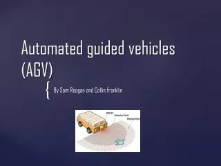
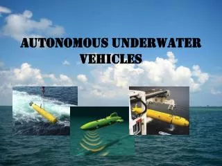
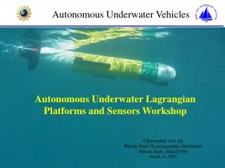
AGV’s Automatic Guided Vehicles (AGV) have been in use since the 1950's. AGVs are driver-less industrial trucks, usually powered by electric motors and batteries. AGVs range in size from carrying small loads of a few kilograms up to loads over 100 tons. The working environment may vary from offices with carpet floor to harbor dockside areas. Most AGV-systems also have system management computers, optimizing the AGV utilization, giving transport orders, tracking the material in transfer and directing the AGV traffic.
Guidance methods • Several methods of guidance and navigation can be implemented. The early AGVs were tracking an inductive guide wire or a visible line, painted or made with tape on the floor. The inductive guide wire is still the most used guiding system for AGVs running on concrete floors, also for new installations. • Many companies and people have tried to invent THE replacement for the inductive guide wire. Recently AGV guiding and navigation systems with laser scanners, microwave transponders, inertia gyros, ultrasonic sensors, embedded magnets, camera vision systems etc. have been launched. • Autonomous guided vehicles require high degrees of intelligence and rigorous control of safety.
Inductive guidance • Inductive guidance (also known as wire guidance) in an AGV uses the fact that an electrical conductor through which an AC current is flowing will create an electromagnetic field around itself. This field is stronger close to the conductor, and is reduced with increased distance from the conductor. • An electromagnetic field, which passes through a coil, will induce an electric voltage across the coil ends. This voltage can be detected across the termination of the coil. The voltage is proportional to the strength of the field. • A guiding antenna contains two coils positioned on each side of the wire, which is embedded in the floor. The difference in electric voltage between the two coils will create the steering signal to the steering motor of the AGV.
Electro-magnetic field This picture shows the principle of guidance by wire, using a receiving antenna with two coils, which detect the electro-magnetic field around the wire in the floor.
Guidance and steering • When the antenna is centered over the guide wire, the voltage in the coils will be the same and the steering signal is equal to zero. If the antenna is positioned to either side of the guide wire, the voltage will be increased in one coil and reduced in the opposite coil. This voltage difference will generate a steering signal, which will control the rotation direction of the steering motor. • The floor loops will have different frequencies that the control board in the AGV can detect separately. • The AGV will have minimum one antenna for guiding and one cross antenna for detecting guide wires that are perpendicular to the guide wire. The cross wires are used to update the exact position of the AGV. Many AGVs will also have further guide antennas for reverse travel and guiding by support leg of a forklift AGV.
Floor installation • The floor installation is made very easy today as there are several companies specializing in this technique. Special floor cutting machines are developed which cut the floor without excessive noise, concrete dust or water spillage and leaves a clean slot ready for installation of the wires. These companies will do the complete floor installation including floor marking, floor cutting, wire installation in floor and enclosures, sealing the slots and grinding if necessary. • Guide wires are installed in a thin slot in the floor. The slot is cut by a concrete cutting machine with a hard metal blade. • The depth of the slot is normally 20 mm, and the width is determined by the number of wires in the slot. Normal width is 4 mm in a normal guide slot and 8 mm if more than three wires are combined in the same slot. • The wire is positioned in the bottom of the slot and a foam strip is squeezed down over the wire for protection. On top of the foam strip a special polyurethane or epoxy filling is added. The filling has a neutral color and is very wear-resistant. • The wire in a guide path may not be positioned close to solid iron constructions for a longer distance, as it will distort the magnetic field. • The guide wires are laid out in the floor in a loop and connected to a frequency generator. There can normally be four different frequencies which each have their own wire loops.
Advantages & disadvantages of wire guidance • Wire guidance is proven technology and is well known by suppliers and users. The AGVE wire guidance system has high accuracy by use of high quality components. The components onboard the AGV are standard components from AGV Electronics. The system is easy to install and program. End users may install and extend existing systems as the technology and programming an AGV is easy to understand. • The AGV Electronics inductive wire guidance is a modern navigation method where floor cutting is minimized. Curves do not normally need to be cut in the floor. Curves may be programmed by using the teach-in function using limited free ranging by dead reckoning. • As a safety feature in an inductive guided system can the guide wire, or a separate control wire, be disconnected to instantly stop all vehicles in a system. • In some cases environmental and system demands make it hard and expensive to install wires in the floor. Under these circumstances other types of navigation methods are used.
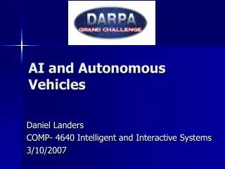
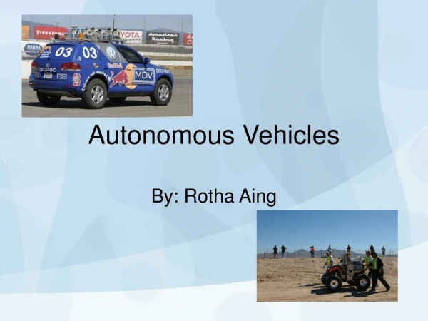
DARPA Grand challenge October 9 , 2005Today Stanley and the Stanford Racing Team were awarded 2 million dollars for being the first team to complete the 132 mile DARPA Grand Challenge course. Stanley finished in just under 6 hours 54 minutes and averaged over 19 miles per hours on the course. The Grand Challenge is an off-road robot competition devised by DARPA (Defense Advanced Research Projects Agency) to promote research in the area of autonomous vehicles. The challenge consists of building a robot capable of navigating 175 miles through desert terrain in less than 10 hours, with no human intervention.
DARPA Challenge winner • The Stanford Vehicle (nicknamed "Stanley") is based on a stock, Diesel-powered Volkswagen Touareg R5, modified with full body skid plates and a reinforced front bumper. Stanley is actuated via a drive-by-wire system developed by Volkswagen of America's Electronic Research Lab. • All processing takes place on seven Pentium M computers, powered by a battery-backed, electronically-controlled power system. The vehicle incorporates measurements from GPS, a 6DOF inertial measurement unit, and wheel speed for pose estimation. • While the vehicle is in motion, the environment is perceived through four laser range finders, a radar system, a stereo camera pair, and a monocular vision system. All sensors acquire environment data at rates between 10 and 100 Hertz. Map and pose information are incorporated at 10 Hz, enabling Stanley to avoid collisions with obstacles in real-time while advancing along the 2005 DARPA Grand Challenge route.