Lecture 6
320 likes | 693 Vues
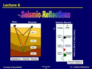
Shot. Receiver. Layer 1. Layer 2. Layer 3. Layer 4. Impedance = Velocity * Density. Lecture 6. Seismic Reflections. Seismic Record. - Trough. + Peak. 0. Layer 1. Impedance Increase. Layer 2. Travel Time (2 way) in msec. Layer 2. Impedance Decrease. Layer 3. Layer 3.

Lecture 6
E N D
Presentation Transcript
Shot Receiver Layer 1 Layer 2 Layer 3 Layer 4 Impedance = Velocity * Density Lecture 6 Seismic Reflections Seismic Record - Trough + Peak 0 Layer 1 Impedance Increase Layer 2 Travel Time (2 way) in msec Layer 2 Impedance Decrease Layer 3 Layer 3 Impedance Increase Layer 4 Peak over Trough is an Increase in Impedance Courtesy of ExxonMobil
The Ideal Seismic Response Able to resolve boundaries of beds a few meters thick 1 meter Increase in Impedance Decrease in Impedance Courtesy of ExxonMobil
Scale for Seismic Data Lamina Although seismic data can not image small-scale stratal units, it can image mid- to large-scale units Lamina Sets Beds Bed Sets Parasequences The big advantage of seismic data is areal coverage Parasequence Sets Sequences Sequence Sets Courtesy of ExxonMobil
Seismic - Units 10s of Meters Thick Predominantly Shale Predominantly Sand Predominantly Shale 10 m Courtesy of ExxonMobil
Rarefaction Compression A A = Amplitude λ λ= Wavelength length, ft or m P= Period time Wave Equation Lingo Dp = Pulse Duration time Period= Time for the waveform to travel 1 wavelength Courtesy of ExxonMobil
Basic Equations 1. P = 1 / f 2.λ = V * P = V / f 3. d = V * T / 2 where P = Period f = Frequency λ= Wavelength V = Velocity d = distance (depth) T = time Courtesy of ExxonMobil
Back to Basics Seismic energy travels down and is reflected off acoustic boundaries Seismic Record Shot Receiver 0.0 0.1 0.2 0.3 0.4 0.5 Increase in impedance 0.6 0.7 0.8 0.9 1.0 1.1 1.2 1.3 Increase in impedance 1.4 Courtesy of ExxonMobil
Reflection Coefficients Seismic Trace Pulse C O N V O L U T I O N Acoustic Structure of the Earth Shot Receiver Imped Low High I1 = 1 * V1 I2 = 2 * V2 I3 = 3 * V3 I4 = 4 * V4 Courtesy of ExxonMobil
That ‘Pesky’ Pulse If the frequency content (Bandwidth) is very large, then the pulse approaches a spike and we can resolve fine-scale stratigraphy Typically the frequency content is limited to about 10 to 50 Hz (BW = 40), which limits our resolution Reflection Coefficients Ideal Pulse Seismic Trace Typical Pulse Seismic Trace Courtesy of ExxonMobil
Types of Pulses Reflection Coefficients Minimum Phase • Causal (real – no motion before wave arrives) • Front loaded • Peak arrival time is frequency dependant • RC is at the first displacement; maximum displacement (peak or trough) is delayed by ¼ λ Courtesy of ExxonMobil
Types of Pulses Reflection Coefficients Zero Phase • Not Causal (not real, since there is motion before the wave arrives) • Symmetric about RC • Peak arrival time is not frequency dependant • Maximum peak-to-side lobe ratio • RC is at the maximum displacement (peak or trough) Courtesy of ExxonMobil
Polarity – Minimum Phase Reflection Coefficients SEG Normal Convention A compression is: • Negative # on the tape • Displayed as a Trough - + SEG = Society of Exploration Geophysics Courtesy of ExxonMobil
Polarity – Zero Phase Reflection Coefficients SEG Normal Convention A compression is: • Positive # on the tape • Displayed as a Peak - + SEG = Society of Exploration Geophysics Courtesy of ExxonMobil
Shot Receiver Layer 1 Boundary Layer 2 What Causes Reflections? • Any interface between bodies with different acoustic properties • Acoustic properties define Impedance (I) , in which I = velocity * density • Small change in impedance – small reflection • Large change in impedance – large reflection Courtesy of ExxonMobil
Time for Two Short Exercises 6a. Calculating Some Reflection Coefficients 6b. Calculating Frequency & Wavelength Courtesy of ExxonMobil
I below – I above I below + I above Seismic Interface Velocity = 2000 m/s Density = 1.7 gm/cc Shale Velocity = 2400 m/s Density = 1.8 gm/cc Sand Reflection Coefficient = = = Courtesy of ExxonMobil
4320 - 3400 I below – I above 4300 + 3400 I below + I above Seismic Interface Velocity = 2000 m/s Density = 1.7 gm/cc I = 2000 * 1.7 = 3400 Shale Velocity = 2400 m/s Density = 1.8 gm/cc I = 2400 * 1.8 = 4320 Sand Reflection Coefficient = = = 0.119 Of the incident energy, 12% is reflected, 88% is transmitted Courtesy of ExxonMobil
I below – I above I below + I above Seismic Interface Velocity = 2000 m/s Density = 1.7 gm/cc Shale Velocity = 2600 m/s Density = 2.1 gm/cc Carbonate Reflection Coefficient = = = Courtesy of ExxonMobil
5460 - 3400 I below – I above 5460 + 3400 I below + I above Seismic Interface Velocity = 2000 m/s Density = 1.7 gm/cc I = 2000 * 1.7 = 3400 Shale Velocity = 2600 m/s Density = 2.1 gm/cc I = 2600 * 2.1 = 5460 Carbonate Reflection Coefficient = = = 0.232 Of the incident energy, 23% is reflected, 77% is transmitted Courtesy of ExxonMobil
Exercise 6b: Frequency & Wavelength Courtesy of ExxonMobil
Stratal Surfaces Unconformities Facies Changes Foreshore/Upper Shoreface Fluvial Incised Valley Fill Coastal Plain Lower Shoreface - Offshore Slope - Basin Submarine Fan Estuarine Condensed Interval Seismic Data & Stratal Surfaces • Seismic reflections parallel stratal surfaces • Reflection terminations mark unconformities • Changes in reflection character indicate facies changes Courtesy of ExxonMobil
Brushy Canyon Formation, West Texas Very Gradational Lateral Changes in Physical Properties Can Have Abrupt Vertical Changes in Physical Properties Especially at PS Boundaries Why Stratal Surfaces? Recall: Reflections are generated where there is a change in acoustic properties (I = rv) • Consider: Where can there be sharp changes in impedance? • horizontally as lithofacies change? • vertically across stratal boundaries? Courtesy of ExxonMobil
G Stratal Surfaces O Unconformities W Facies Changes Not Every Reflection is Strata! There are other seismic reflections out there that may not be stratigraphic in origin • Fluid Contacts • Fault Planes • Multiples • Others Courtesy of ExxonMobil
Another Exercise 6c. Generating a Modeled Seismic Trace Courtesy of ExxonMobil
Exercise 6c: A Synthetic Trace The Pulse 3 Ref. Coeff. Courtesy of ExxonMobil


