Download
1 / 10
100 likes | 121 Vues
This innovative system utilizes a camera and Raspberry Pi to detect and transmit hazard coordinates from a rocket to a ground station. Precise testing procedures ensure compliance and accuracy. Real-time analysis and human verification guarantee reliable hazard identification.

E N D
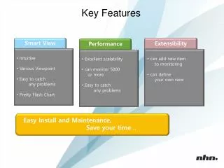
Discuss key design features • Camera takes video of the ground below the rocket, Pi pulls stills from the video feed • Image is smoothed and then posterized • Colors in image are divided into “background” and “hazard” groups based on their frequency in the picture • Sections of image identified as hazard are segmented into blobs and given image coordinates • GPS data is combined with image coordinate data to give global hazard coordinates • Hazard coordinates are sent via radio link to ground station
Test plans and procedures • Test each component prior to combination for compliance • Test radio system for range compliance • Test battery for charge duration • Test camera for resolution and focus range • Test Raspberry Pi for image analysis throughput • Images will be analyzed by TAP for hazards, and human-verified for accuracy • TAP will be taken to altitude to analyze live terrain, and global hazard coordinates will be human-verified for accuracy
Final Payload Design Overview Table 1: TAP component specifications
Final Payload Design Overview Continued Bulkhead Outer Casing Camera Cover Threaded Rod Raspberry Pi Figures 1,2: Cutaway views of TAP bay
Final Payload Design Overview Continued Figure 7: Ground station TAP schematic Figure 6: On-board TAP Schematic
Final Payload Design Overview Continued IMU data is acquired via I2C bus and GPS via USB Apogee is detected by monitoring altitude Image is acquired from camera over USB The image is smoothed with a Gaussian filter to reduce noise Color space is changed from RGB to HSx to account for variable lighting conditions Images and hazards are logged for offline analysis and debugging Real-world position of hazards is calculated using camera geometry and GPS data K-means is used to reduce the number of colors in the image Hazard pixels are clustered together into blobs Based on the frequency of the color, each pixel is classified as hazard or non-hazard Hazard locations are reported over radio link Figure 3: TAP Algorithm
Final Payload Design Overview Continued Figures 4,5: (Left) On-Board block diagram; (Right) Ground Station Block Diagram
4 Payload Integration • The TAP bay will be mounted directly above the engine compartment to minimize the amount of rocket body in the field of view • ASP and TAP programs will both be stored on one Raspberry Pi, since the two programs are active during separate portions of the flight, and share sensor requirements • The XBee 900 will be mounted on the exterior of the rocket using an adhesive • TAP components will be mounted on a plate, which will be attached to threaded rods and secured to bulkheads at both ends of the bay 4 3 2
Interfaces • TAP will be activated by an internal switch • An LED mounted within the camera shell will show when the Camera is powered • An internal buzzer will sound when the Raspberry Pi completes its boot sequence • The XBee 900 will transmit hazard data wirelessly to the ground station • The ground station will display the hazard location to the LTRL team
Status of Requirements Verification (TAP) Table 2: Requirements and verification