Computer Architecture Out-of-order Execution
700 likes | 1.07k Vues
Computer Architecture Out-of-order Execution. By Yoav Etsion With acknowledgement to Dan Tsafrir , Avi Mendelson , Lihu Rappoport , and Adi Yoaz. The need for speed: Superscalar. Remember our goal: minimize CPU Time CPU Time = duration of clock cycle CPI IC

Computer Architecture Out-of-order Execution
E N D
Presentation Transcript
Computer ArchitectureOut-of-order Execution By YoavEtsionWith acknowledgement to Dan Tsafrir, AviMendelson, LihuRappoport, and AdiYoaz
The need for speed: Superscalar • Remember our goal: minimize CPU Time CPU Time = duration of clock cycle CPI IC • So far we have learned that in order to • Minimize clock cycle add more pipe stages • Minimize CPI utilize pipeline • Minimize IC change/improve the architecture • Why not make the pipeline deeper and deeper? • Beyond some point, adding more pipe stages doesn’t help, because • Control/data hazards increase, and become costlier • (Recall that in a pipelined CPU, CPI=1 only w/o hazards) • So what can we do next? • Reduce the CPI by utilizing ILP (instruction level parallelism) • We will need to duplicate HW for this purpose…
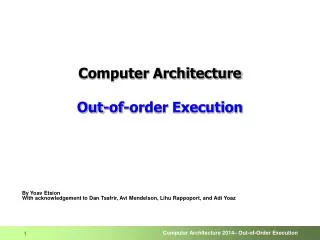
IF ID EXE MEM WB IF ID EXE MEM WB A simple superscalar CPU • Duplicates the pipeline to accommodate ILP (IPC > 1) • ILP=instruction-level parallelism • Note that duplicating HW in just one pipe stage doesn’t help • e.g., when having 2 ALUs, • the bottleneck moves to other stages • Conclusion: • Getting IPC > 1 requires to fetch/decode/exe/retire >1 instruction per clock:
u-pipe IF ID pairing? v-pipe Example: Pentium Processor • Pentium fetches & decodes 2 instructions per cycle • Before register file read, decide on pairing • Can the two instructions be executed in parallel? (yes/no) • Pairing decision is based… • On data dependencies (instructions must be independent) • On resources (v-pipe can only execute some of the instructions; and also, some instruction use resources from both pipes)
Is superscalar good enough? • A superscalar processor can fetch, decode, execute, and retire, e.g., 2 instructions in parallel • But… • Can execute only independent instructions in parallel • Whereas adjacent instructions are often dependent • So the utilization of the second pipe is often low • Solution: out-of-order execution • Execute instructions based on the “data flow” graph,(rather than program order) • Still need to keep the semantics of the original program
Out-of-order in a nutshell • HW examines a sliding window of consecutive instructions • The “instruction window” • Ready instructions get picked up from window • Executed out of program order • Instruction results are committed to the machine state (memory+reg. file) in original program order • Why? • User is unaware (except that the program runs faster)
Data Flow Graph r5 r6 r1 r8 r4 1 4 5 6 2 1 3 6 3 5 2 4 Out-of-order execution Superscalar basics: Data flow analysis • Example: (1)r1 r4 / r7 /* assume division takes 20 cycles */ (2) r8r1 + r2 (3) r5 r5 + 1 (4) r6 r6 - r3 (5) r4 r5 + r6 (6) r7 r8 * r4 In-order execution In-order (2-way superscalar) 6 1 2 3 4 5 4 1 2 5 6 3
OoO – general scheme • Fetch & decode in order • Multiple instructions are fetched/decoded in parallel • Insts. put in reservation stations (RS) • Execute instructions that are ready in the reservation stations • Instruction operands must be ready • Available execution resources • Following execution: • Broadcast result on bypass network • Signal all dependent instructions that data is ready • Commit instructions in-order • Can commit an instruction only after all preceding instructions (in program order) have committed
Out of order execution (OoO) • Advantages: Better performance! • Exploit Instruction Level Parallelism (ILP) • Hide latencies (e.g., L1 data cache miss, divide) • Disadvatages: • HW is much more complex than that of in-order processors • Can compilers do this work? • In a very limited way – can only statically schedule instructions (VLIW) • Compilers lack runtime information • Conditional branch direction (→ compiler limited to basic blocks) • Data values, which may affect calculation time and control • Cache miss / hit The key is dynamic analysis and resolution of data dependencies
6 9 5 7 10 12 11 13 8 OoO: data dependencies • Example: (1) r8 20(2) r1 addr1(3) r2 addr2 (4) r3addr3 LOOP:(5) r4 MEM[r1] (6) r1 r1 + 4 (7) r5 MEM[r2] (8) r2 r2+ 4 (9) r6r4+ r5 (10) MEM[r3] r6 (11) r3 r3+ 4 (12) r8 r8 - 1 (13) bnzr8, LOOP Instruction dependence graph r8 r2 r1 r4 r5 r6 r3 Are all dependencies equal?
Data dependency types (I) • True dependence: RaW(Read-after-Write)(7) r5 MEM[r2] (9) r6r4 + r5 • An instruction consumes data that was produced by an earlier instruction • Can we eliminate such dependencies? • Not without a time machine… (or value speculation)
6 9 5 7 10 12 11 13 8 RaW examples (1) r8 20(2) r1 addr1(3) r2 addr2 (4) r3 addr3 LOOP:(5) r4 MEM[r1] (6) r1 r1 + 4 (7) r5 MEM[r2] (8) r2 r2+ 4 (9) r6r4+ r5 (10) MEM[r3] r6 (11) r3 r3+ 4 (12) r8 r8 - 1 (13) bnzr8, LOOP r8 r2 r1 r4 r5 r6 r3
Data dependency types (II) • Anti-dependence: WaR(Write-after-Read)(5) r4 MEM[r1] (6) r1 r1 + 4 • False dependence: WaW(Write-after-Write)(7) r5 MEM[r2](7*) r5MEM[r2] // * next iteration • Can we eliminate such dependencies? • Yes! if we divert the second write to an alternate storage location • Also known as Register Renaming
6 9 5 7 10 12 11 13 8 WaR examples (1) r8 20(2) r1 addr1(3) r2 addr2 (4) r3 addr3 LOOP:(5) r4 MEM[r1] (6) r1 r1 + 4 (7) r5 MEM[r2] (8) r2 r2+ 4 (9) r6r4+ r5 (10) MEM[r3] r6 (11) r3 r3+ 4 (12) r8 r8 - 1 (13) bnzr8, LOOP r8 r2 r1 r4 r5 r6 r3
9 9 6 6 5 5 7 7 10 10 12 12 11 11 13 13 8 8 WaW examples 1st iteration:(5) r4 MEM[r1] (6) r1 r1 + 4 (7) r5 MEM[r2] (8) r2 r2+ 4 (9) r6r4+ r5 (10) MEM[r3] r6 (11) r3 r3+ 4 (12) r8 r8 - 1 (13) bnzr8, LOOP 2nd iteration:(5) r4 MEM[r1] (6) r1 r1 + 4 (7) r5 MEM[r2] (8) r2 r2+ 4 (9) r6r4 + r5 (10) MEM[r3] r6 (11) r3 r3 + 4 (12) r8 r8 - 1 (13) bnzr8, LOOP r8 r2 r1 r4 r5 r6 r3 r8 r2 r1 r4 r5 r6 r3
OoO: Main ingredients • Wide fetch/issue/decode/commit • If only one inst. goes into the pipeline each cycle, then on average only one inst. will commit each cycle IPC=1 • Branch prediction • Not much parallelism in basic blocks (insts. seq. between branches) • Identify ILP across branch (and loop) boundaries • Register renaming • Break False- and Anti-dependencies • Speculative execution • Speculate branch outcome without affecting correctness
OoO Pipeline • Fetch • Branch prediction • Decode • Register renaming • Reservation stations (RS) • Instructions wait for the inputs • Instructions wait for functional units • Functional units (FU) • Bypass network • Broadcast computed values back to reservation stations and PRF • Reorder buffer (ROB) • De-speculate execution, mostly by Committing instructions in-order • The instruction window is instantiated as RS & ROB
6 9 9 6 5 5 7 7 10 10 12 12 11 11 13 13 8 8 Benefits of Register Renaming 1st iteration:(5) r4 MEM[r1] (6) r1 r1 + 4 (7) r5 MEM[r2] (8) r2 r2+ 4 (9) r6r4+ r5 (10) MEM[r3] r6 (11) r3 r3+ 4 (12) r8 r8 - 1 (13) bnzr8, LOOP 2nd iteration:(5) r4 MEM[r1] (6) r1 r1 + 4 (7) r5 MEM[r2] (8) r2 r2+ 4 (9) r6r4 + r5 (10) MEM[r3] r6 (11) r3 r3 + 4 (12) r8 r8 - 1 (13) bnzr8, LOOP r8 r2 r1 r4 r5 r6 Critical path: 8 instructions r3 r8 r2 r1 r4 r5 r6 Remove WaW Remove WaR r3 Result…
6 9 9 5 5 7 7 10 10 12 12 11 11 13 13 8 Benefits of Register Renaming 1st iteration:(5) r4 MEM[r1] (6) r1 r1 + 4 (7) r5 MEM[r2] (8) r2 r2+ 4 (9) r6r4+ r5 (10) MEM[r3] r6 (11) r3 r3+ 4 (12) r8 r8 - 1 (13) bnzr8, LOOP 2nd iteration:(5) r4 MEM[r1] (6) r1 r1 + 4 (7) r5 MEM[r2] (8) r2 r2+ 4 (9) r6r4 + r5 (10) MEM[r3] r6 (11) r3 r3 + 4 (12) r8 r8 - 1 (13) bnzr8, LOOP r8 r4 r5 r2 r1 r8 r6 r4 r5 r3 r6 New critical path: 4 instructions!
Register renaming: How does it work? • Data is stored in a physical register file (PRF) • Architected register file (ARF) holds pointers to PRF registers • Each register in ARF represents a register in the ISA • Registers in ARF point to the latest version of the datum in PRF • An instruction that writes to a register triggers a “rename” operation • Allocate new PRF register • Update pointer in ARF • Naturally, PRF > ARF • Note: Other methods to implementregister renaming have been proposedin the past… ARF PRF r1 r2 r3 r4 r32
Register renaming: Example PRF Original code:(5) r4 MEM[r1] (6) r1 r1 + 4 (7) r5 MEM[r2] (8) r2 r2+ 4 (9) r6r4+ r5 (10) MEM[r3] r6 (11) r3 r3+ 4 (12) r8 r8 - 1 (13) bnzr8, LOOP Post-decode(as seen by RS):(5) pr5 MEM[40] (6) pr6 40+ 4 (7) pr7 MEM[120] (8) pr8 120+ 4 (9) pr9pr5+ pr7 (10) MEM[200] pr9 (11) pr10 200+ 4 (12) pr11 20- 1 (13) bnzpr11, LOOP ARF pr1 40 pr9 X r1 pr2 120 r2 pr10 X pr3 200 pr11 X r3 r4 pr4 20 pr12 X r5 pr5 pr13 pr6 pr14 r6 X pr7 pr15 r7 X r8 pr8 X pr16
OoO Pipeline: Execution • Fetch • Branch prediction • Decode • Register renaming • Reservation stations (RS) • Instructions wait for the inputs • Instructions wait for functional units • Functional units (FU) • Bypass network • Broadcast computed values back to reservation stations and PRF • Reorder buffer (ROB) • De-speculate execution, mostly by Committing instructions in-order • The instruction window is instantiated as RS & ROB
Out-of-order execution • Insts. registered in ROB • ROB acts like a cyclic buffer • Decoded insts. sent to RS • If operands a ready, inst. is sent to FU • Otherwise, listen on bypass network and wait for operands • Values sent on bypass network are tagged by phys. Register • Executed insts. are marked in ROB as completed • Computed value is sent over bypass network to consumers
6 9 5 7 10 12 11 13 8 OoO execution example Instructions waiting in reservation stations: (5) pr5 MEM[40] (6) pr6 40+ 4 (7) pr7 MEM[120] (8) pr8 120+ 4 (9) pr9pr5+ pr7 (10) MEM[200] pr9 (11) pr10 200+ 4 (12) pr11 20- 1 (13) bnzpr11, LOOP broadcast pr5 &pr8 (9) receives pr5 broadcastpr6&pr7 (9) receives pr7 broadcastpr9&pr11 (10) receives pr9 (13) receives pr11 pr11 pr5 pr7 pr9 Instructions execute as soon as their operands become ready, rather than in program order
OoO Pipeline: ROB & de-speculation • Fetch • Branch prediction • Decode • Register renaming • Reservation stations (RS) • Instructions wait for the inputs • Instructions wait for functional units • Functional units (FU) • Bypass network • Broadcast computed values back to reservation stations and PRF • Reorder buffer (ROB) • De-speculate execution, mostly by Committing instructions in-order • The instruction window is instantiated as RS & ROB
Managing speculative execution • Insts. must not affect machine state while they are speculative • Mis-predicted paths need to be flushed • Precise interrupts • Traps/Exceptions/Interrupts leave pipeline in well-known state • As if the offending instruction just executed • Renamed registers must not be freed until a path is validated • In practice, ARF is saved (checkpoint) whenever the decoder encounters a branch instruction
Managing speculative execution • Common implementation: • Fetch/Decode instructions from the predicted execution path • Instructions can execute as soon as their operands become ready • Instructions can graduate and commit to memory only once it is certain they should have been executed • An instruction commits only when all previous (in-order) instructions have committed instructions commit in-order • Instructions on a mis-predicted execution path are flushed
Example: Managing speculation Instructions in ROB (5) pr5 MEM[40] (6) pr6 40 + 4 (7) pr7 MEM[120] (8) pr8 120+ 4 (9) pr9pr5 + pr7 (10) MEM[200] pr9 (11) pr10 200 + 4 (12) pr11 20 - 1 (13) bnzpr11, LOOP (5) pr5 MEM[40] (6) pr6 40 + 4 (7) pr7 MEM[120] (8) pr8 120+ 4 (9) pr9pr5 + pr7 (10) MEM[200] pr9 (11) pr10 200 + 4 (12) pr11 20 - 1 (13) bnzpr11, LOOP • ROB contains both normal and speculative insts. • Some have already executed • Can we commit any? • Remember: some insts. might fail • Memory faults/exceptions • Divide-by-zero • Cannot commit younger insts., even if branches were resolved • Only the oldest executed instructions can commit • Multiple insts. per cycle (n-way) ? ? ? ? Speculative path ? ?
Scalability of Speculative Execution • Examining a large instruction window requires highly accurate branch prediction • Example: • Window size: 150 insts. • 30 branches to fill a window (avg. of branch every 5 instruction) • Case 1: Prediction rate=95% • Probability to predict 30 branches: 0.95^30=0.22 • Case 2: Prediction rate=98% • Probability to predict 30 branches: 0.98^30=0.55 • Case 2: Prediction rate=99% • Probability to predict 30 branches: 0.99^30=0.74
OoO scalability: VLSI considerations • Many large ported arrays • Register files (ARF and PRF) • Reservation stations • For example, a 4-way OoO pipeline requires: • Reg. files with 8 RD ports and 4 WR ports (decode width) • RS and ROB with 4 ports each (execute/commit width) • More logic is needed, and it is more complex • Examples: • Register renaming • Wakeup logic in RS (which instructions are selected to run?) • All reservation stations must be checked whenever a FU broadcasts a tagged result • Many, many comparators
OoO scalability: VLSI considerations • Very wide buses • Multiple results sent on the bypass network on each cycle • Timing is a challenge - need additional pipe stages • Rename analysis • Rename sources • Access available sources from committed register file • Allocate entry in reservation station • “Ready” Decision Balancing the machine is essential and complex
OoO summary • Advantages • Help exploit Instruction Level Parallelism (ILP) • Help hide latencies (e.g., cache miss, divide) • Superior/complementary to inst. Scheduler in the compiler • Dynamic instruction window • Complex micro-architecture • Complex wakeup logic (instruction scheduler) • Requires reordering mechanism (retirement) in the back-end for: • Precise interrupt resolution • Misprediction/speculation recovery • Speculative Execution • Advantage: larger scheduling window reveals more ILP • Issues: • Complex logic needed to recover from mis-prediction • Runtime cost incurred when recovering from a mis-prediction
OoO summary • First appeared in floating point unit of IBM mainframes • Tomasulo’s algorithm, published in 1967 • Generalized by Patt, Hwu and Shebanow [1985] • After that, quickly adopted by industry • DEC Alpha, Intel Pentium Pro • Today it is ubiquitous: • Intel: 4-way OoO; instruction windows up to 150-200 insts. • AMD: 4-way OoO; instruction windows of ~70 insts. • ARM (Cortex-A9/A15): 2/5-way OoO; instruction window 40-100+ • Many ARM implementations exist… • Numerous variations and optimizations and extensions have been studied, and are used in commercial products
OOO Processor Example The P6 Microarchitecture
The P6 family (i686) • Features • 1st out of order x86 (=> data flow analysis) • Speculative execution (across branches; requires flush+recovery) • Multiple branch prediction (wide op window contains 5 branch on avg) • Register renaming (solves false dependencies, gives more regs) • Super-pipeline: ~12 pipe stages (P-IV had 31! i7 back to 14) *off die ** size of smallest part is smaller than the feature size
The P6 family (i686) • Was used until 2011: • MacBook Air (1.4GHz Core 2 Duo) • Due to relative low power consumption • Clock frequency ~proportional to feature size • After P-III came P-IV… which wasn’t ideal for mobile computing • Much (not all) of the improvement comes from feature size minimization *off die ** size of smallest part is smaller than the feature size
Chip logically partitioned to 3 • Front end • In order, get and ops from memory • Decode them + turn them • from CISC ops • to >=1 u-ops (RISC-like) • So x86 input=CISC, but internally it’s actually RISC • The front-end is responsible for making the transition • Core • Out of order, speculative, superscalar, renames registers • Retire • In order • Commits when speculation ends • Can simultaneously commit up to 3 ops (“width” of machine)
External Bus L2 MOB BIU DCU MIU IFU AGU R IEU BPU S I FEU D MS ROB RAT P6 Arch • In-Order Front End • BIU: Bus Interface Unit • IFU: Instruction Fetch Unit (includes IC) • BPU: Branch Prediction Unit • ID: Instruction Decoder • MS: Micro-Instruction Sequencer • RAT: Register Alias Table • Out-of-order Core • ROB: Reorder Buffer • RRF: Real Register File • RS: Reservation Stations • IEU: Integer Execution Unit • FEU: Floating-point Execution Unit • AGU: Address Generation Unit • MIU: Memory Interface Unit • DCU: Data Cache Unit • MOB: Memory Order Buffer • L2: Level 2 cache • In-Order Retire
External Bus L2 MOB BIU DCU MIU IFU AGU R IEU BPU S I FEU D MS ROB RAT P6 Arch In-Order Front End • BIU: Bus Interface Unit(fetches instructions) • IFU: Instruction Fetch Unit (includes i-cache) • BPU: Branch Prediction Unit • ID: Instruction Decoder • MS: Micro-Instruction Sequencer(complex ops are comprised of a sequence of μ-ops; simple ops are comprised of only 1 μ-op) • RAT: Register Alias Table(solves false dep.; most recent arch => physical mapping)
External Bus L2 MOB BIU DCU MIU IFU AGU R IEU BPU S I FEU D MS ROB RAT P6 Arch Out-of-order Core • L2: Level 2 cache • MOB: Memory Order Buffer • DCU: Data Cache Unit • MIU: Memory Interface Unit • AGU: Address Generation Unit • RRF: “Real” Register File(not shown; the machine’s state) • IEU: Integer Execution Unit • FEU: Floating-point Execution Unit • RS: Reservation Stations(All those ops whose dependencies aren’t yet met; up to 20; 5 ports to exe units) • ROB: Reorder Buffer(The physical regs; one entry per op – the reg is the dest of the op; in order!)
Next IP Reg Ren RS Wr Icache Decode I1 I2 I3 I4 I5 I6 I7 I8 P6 pipeline - 12 stages (10<=P6<=14) RS dispatch In-Order Front End Ex [O1] [O2] [R1] [R2] 1:Next IP 2: ICache lookup 3: ILD (instruction length decode) 4: rotate 5: ID1 (instruction decoded 1) 6: ID2 (instruction decoded 2) 7: RAT - rename sources & ALLOC - assign destinations 8: ROB - read sources RS - schedule data-ready uops for dispatch 9: RS - dispatch uops 10:EX 11-12: Retirement O1 O2 Out-of-order Core Retirement R1 R2 In-order Retirement
In-order front-end Bytes Instructions uops BPU Next IP Mux MS • BPU – Branch Prediction Unit – predict next fetch address • IFU – Instruction Fetch Unit • iTLB translates virtual to physical address (next lecture) • ICache supplies 16byte/cyc (on miss: access L2, maybe memory) • ILD – Instruction Length Decode – split bytes to instructions • IQ – Instruction Queue – buffer the instructions • ID – Instruction Decode – decode instructions into uops • MS – Micro-Sequencer – provides uops for complex instructions • IDQ – Instruction Decode Queue – buffer the uops ILD ID IFU IQ IDQ
Branch prediction • Implementation • Use local history to predict direction • Need to predict multiple branches • Need to predict branches before previous branches are resolved • Branch history updated first based on prediction, later based on actual execution (speculative history) • Target address taken from BTB • Prediction rate: ~92% • High prediction rate is crucial for long pipelines • Especially important for OOOE, speculative execution: • On misprediction all instructions following the branch in the instruction window are flushed • Effective size of the window is determined by prediction accuracy
Jump out of the line Jump into the fetch line jmp jmp jmp jmp Predict taken Predict not taken Predict taken Predict taken Branch prediction – clustering • Given a fetched line (bytes), need to know which line to fetch next • Perhaps there’s more than one branch in the line • We must use 1st (leftmost) taken branch (>= the current fetched IP) • Implemented by • Splitting IP into setOfLine + tagOfLine + offsetWithinLine • If there’s a match • The offsets of the matching ways are ordered • Ways with offset smaller than the fetch IP offset are discarded • The 1st branch that’s predicted taken is chosen as the predicted branch IP line
offset 1001 0 counters Tag Target ofst Hist V T P IP LRR 9 Pred= msb of counter 4 1 2 1 4 2 9 32 32 128 sets 15 Branch Type 00- cond 01- ret 10- call 11- uncond Return Stack Buffer Per-Set Way 1 Way 3 Way 0 Way 2 P6 BTB • 2-level, local histories, per-set counters • 4-way set associative: 512 entries in 128 sets • Up to 4 branches can have the same set/tag match (since there are 4 ways)
D0 D1 D2 D3 4 uops 1 uop 1 uop 1 uop In-order front-end – decoder Determine where each x86 op starts 16 Instruction bytes from IFU Buffers ops in queue Instruction Length Decode • Convert ops into uops • D0 handles complex ops (translate to up to 4 uops) • D1-3 for simple ops that translate to 1uop • In case ops aligned with D1-3 decode into >1 uops, defer them to following cycle (whereby D0 will be used) IQ • Buffers uops • Smooth decoder’s variable throughput (we want the same number of uops every cycle (=4)) IDQ
Micro operations (uops) • Each CISC inst is broken into one or more RISC uops • Simplicity • Each uop is (relatively) simple • Canonical representation of src/dest (2 src, 1 dest) • But increased instruction count • Simple instructions translate to a few uops • Typical uop count (not necessarily cycle count!) Reg-Reg ALU/Mov inst: 1 uop Mem-Reg Mov (load) 1 uop Mem-Reg ALU (load + op) 2 uops Reg-Mem Mov (store) 2 uops (st addr, st data) Reg-Mem ALU (ld + op + st) 4 uops • Complex instructions translate into more uops
External Bus L2 MOB BIU DCU MIU IFU AGU R IEU BTB S I FEU MIS D ROB RAT Out-of-order core: ROB + RS • Reorder Buffer (ROB): • Holds all “not yet retired” instructions • 40 ordered entries (cyclic array) • Retired in-order • It’s possible some instruction already executed (their result known), but cannot be retired since • still have speculative status • and/or are waiting for previous instructions to retire in order • Reservation Stations (RS): • Holds “not yet executed” instructions • 20 entries (subset of ROB) • Up to 4 simultaneous ops can get in and out of RS simultaneously • After execution • Results written to both ROB & possibly to RS (when source of other instructions)
External Bus L2 MOB BIU DCU MIU IFU AGU R IEU BTB S I FEU MIS D ROB RAT Out-of-order core: execution units • Basic execution units (*EU; *=I|F) • IEU: Integer Execution Unit • FEU: Floating-point Execution Unit • Memory-related execution units • DCU: Data Cache Unit • AGU: Address Generation Unit • Computes effective address & sends to DCU to fetch from cache) • MOB: Orders memory loads and stores • L2: Level 2 cache • MIU: Memory Interface Unit • MIU feeds execution units • Positioned between RS & exe units • Has 5 ports (see next slide) • Some units may be similar between ports, others exclusive
Out-of-order core: execution units internal 0-dealy bypass within each EU 1st bypass in MIU 2nd bypass in RS SHF FMU RS MIU FDIV IDIV FAU IEU Port 0 JEU IEU Port 1 Port 2 Bypass: shorten path of source to exe unit, e.g., ifcurrent outcome of a certain exe unit is its sourcefor next round, can use outcome directly, etc. AGU Load Address Port 3,4 Store Address AGU SDB DCU