Computer Architecture Out-of-order execution
490 likes | 793 Vues
Computer Architecture Out-of-order execution. By Dan Tsafrir, 28/5/2012 Presentation based on slides by David Patterson, Avi Mendelson, Lihu Rappoport, and Adi Yoaz. Out-of-order in a nutshell. Real processors Do not really serially execute instruction by instruction

Computer Architecture Out-of-order execution
E N D
Presentation Transcript
Computer ArchitectureOut-of-order execution By Dan Tsafrir, 28/5/2012Presentation based on slides by David Patterson, Avi Mendelson, Lihu Rappoport, and Adi Yoaz
Out-of-order in a nutshell • Real processors • Do not really serially execute instruction by instruction • Instead, they have an “instruction window” • Moves across the program • Ready instructions get picked up from window • Not necessarily in program order • Need window because some instructions aren’t ready • User is unaware (except that the program runs faster)
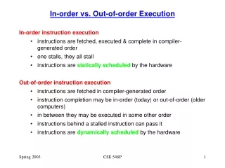
What’s next • Remember our goal: minimize CPU Time CPU Time = duration of clock cycle CPI IC • So far we have learned that in order to • Minimize clock cycle add more pipe stages • Minimize CPI utilize pipeline • Minimize IC change/improve the architecture • Why not make the pipeline deeper and deeper? • Beyond some point, adding more pipe stages doesn’t help, because • Control/data hazards increase, and become costlier • (Recall that in a pipelined CPU, CPI=1 only w/o hazards) • So what can we do next? • Reduce the CPI by utilizing ILP (instruction level parallelism) • We will need to duplicate HW for this purpose…
IF ID EXE MEM WB IF ID EXE MEM WB A superscalar CPU • Duplicates HW to accommodate ILP (IPC > 1) • Note that duplicating HW in just one pipe stage doesn’t help • e.g., when having 2 ALUs, • the bottleneck moves to other stages • Conclusion: • Getting IPC > 1 requires to fetch/decode/exe/retire >1 instruction per clock:
u-pipe IF ID pairing? v-pipe Example: Pentium Processor • Pentium fetches & decodes 2 instructions per cycle • Before register file read, decide on pairing • Can the two instructions be executed in parallel? (yes/no) • Pairing decision is based… • On data dependencies (instructions must be independent) • On resources (v-pipe can only execute some of the instructions; and also, some instruction use resources from both pipes)
Misprediction penalty for superscalar CPUs • MPI = miss-per-instruction ; MPR = miss-predict rate #incorrectly predicted branches #predicted branches MPI = = MPR× total # of instructions total # of instructions • MPI correlates well with performance; e.g., assume: • MPR = 5%, branches/instrctutions = 20% MPI = 1% • Without hazards, IPC=2 (2 instructions per cycles) • Flush penalty of 10 cycles • We get: • MPI = 1% flush in every 100 instructions, but • IPC=2 flush every 100/2 = 50 cycles • 10 cycles flush penalty every 50 cycles • 20% in performance • (For IPC=1, we would have had • 10 cycles flush penalty per 100 cycles 10% in performance)
Is superscalar good enough? • A superscalar processor can fetch, decode, execute, and retire, e.g., 2 instructions in parallel • But… • Can execute only independent instructions in parallel • Whereas adjacent instructions are often dependent • So the utilization of the second pipe is often low • Solution: out-of-order execution • Execute instructions based on the “data flow” graph,(rather than program order) • Still need to keep the semantics of the original program
Out of order execution (OOOE) • Look ahead in a window of instructions andfind instructions that are “ready” to execute: • Don’t depend on data from previous instructions still not executed • Resources are available • Can be executed before previous (unexecuted) instuctions • Advantages: • Help exploit Instruction Level Parallelism (ILP) • Help hide latencies (e.g., L1 data cache miss, divide) • Can compilers do this work? • Not really. Compilers can statically reschedule instructions • Compilers lack runtime information • Conditional branch direction (→ compiler limited to basic blocks) • Data values, which may affect calculation time and control • Cache miss / hit
Data Flow Graph r5 r6 r1 r8 r4 In-order (superscalar 3) 1 3 1 4 6 5 2 1 2 3 5 2 6 5 3 6 4 4 Out-of-order execution Data flow analysis • Example: (1)r1 r4 / r7 /* assume divide takes 20 cycles */ (2) r8r1 + r2 (3) r5 r5 + 1 (4) r6 r6 - r3 (5) r4 r5 + r6 (6) r7 r8 * r4 In-order execution 4 2 6 1 3 5
Retire (commit) Instruction pool Fetch & Decode In-order In-order Execute Out-of-order OOOE – general scheme • Fetch & decode instructions in parallel but in order, to fill inst. pool • Execute ready instructions from the instructions pool • All the data required for the instruction is ready • Execution resources are available • Once an instruction is executed • Signal all dependent instructions that data is ready • Commit instructions in parallel but in-order • Can commit an instruction only after all preceding instructions (in program order) have committed
1 3 4 2 5 OOOE – dependency types • Assume that executing a divide operation takes 20 cycles (1) r1 r5 / r4 (2) r3r1 + r8 (3) r8 r5 + 1 (4) r3 r7 - 2 (5) r6 r6 + r7 • Inst2 has a RAW (read after write) dependency on r1 of Inst1 • It really cannot be executed in parallel with Inst1 • Can later instructions “pass” Inst2? • Inst3 cannot since Inst2 must read r8before Inst3 writes to it (WAR) • Inst4 cannot since it must write to r3 after Inst2 (WAW) • Inst5 can
OOOE – false dependencies • “Write after” dependencies • WAR: write to a register which is read by an earlier inst. (1) r3 r2 + r1 (2) r2 r4 + 3 • WAW: write to a register which is written by an earlier inst. (1) r3 r1 + r2 (2) r3 r4 + 3 • These are false dependencies • There is no missing data • Still prevent executing instructions out-of-order • Solution: “register renaming”
Register renaming • Hold a pool of “physical” registers (users are unaware) • Map architectural registers into physical registers • Before an instruction can be sent for execution • Allocate a free physical register from a pool • The physical register points to the architectural register • When an instruction writes a result • Write the result value to the physical register • When an instruction needs data from a register • Read data from the physical register allocated to the latest inst which writes to the same arch register, and precedes the current inst • If no such instruction exists, read directly from the arch. register • When an instruction commits • Move the value from the physical register to the arch register it points
WAW WAW WAR OOOE with register renaming– example cycle 1cycle 2 (1) r1 mem1 r1’ mem1 (2) r2 r2 + r1 r2’ r2 + r1’ (3) r1 mem2 r1” mem2 (4) r3 r3 + r1 r3’ r3 + r1” (5) r1 mem3 r1”’ mem3 (6) r4 r5 + r1 r4’ r5 + r1”’ (7) r5 2 r5’ 2 (8) r6 r5 + 2 r6’ r5’ + 2 Register Renaming Benefits • Removes false dependencies • Removes architecture limit for # of registers WAR WAR
Executing beyond branches • So far we do not look for instructions ready to execute beyond a branch • Limited to the parallelism within a “basic-block” • A basic-block is ~5 instruction long (1)r1 r4 / r7 (2) r2 r2 + r1 (3) r3r2 - 5 (4) beq r3,0,300 If the beq is predicted NT, (5) r8 r8 + 1 Inst 5 can be spec executed • We would like to look beyond branches • But what if we execute an instruction beyond a branch and then it turns out that we predicted the wrong path ? Solution: “speculative execution”
Speculative execution • Execution of instructions from a predicted (yet unsure) path • Eventually, path may turn wrong • Implementation: • Hold a pool of all not yet executed instructions • Fetch instructions into the pool from a predicted path • Instructions for which all operands are ready can be executed • An instruction may change the processor state (commit) only when it is safe • An instruction commits only when all previous (in-order) instructions have committed instructions commit in-order • Instructions which follow a branch commit only after the branch commits • If a predicted branch is wrong all the instructions which follow it are flushed • Register renaming helps speculative execution • Renamed registers are kept until speculation is verified to be correct
WAW WAW Speculative Execution WAR Speculative execution – example cycle 1cycle 2 (1) r1 mem1 r1’ mem1 (2) r2 r2 + r1 r2’ r2 + r1’ (3) r1 mem2 r1” mem2 (4) r3 r3 + r1 r3’ r3 + r1” (5) jmp cond L2 predicted taken to L2 (6)L2 r1 mem3 r1”’ mem3 (7) r4 r5 + r1 r4’ r5 + r1”’ (8) r5 2 r5’ 2 (9) r6 r5 + 2 r6’ r5’ + 2 • Instructions 6-9 are speculatively executed • If the prediction turns wrong, they will be flushed • If the branch was predicted not-taken • The instructions from the other path would have been speculatively executed
OOOE – summary • Advantages • Help exploit Instruction Level Parallelism (ILP) • Help hide latencies (e.g., cache miss, divide) • Superior/complementary to compiler scheduler • Dynamic instruction window • Regs renaming: can use more than the number of arch registers • Complex micro-architecture • Complex scheduler • Requires reordering mechanism (retirement) in the back-end for: • Precise interrupt resolution • Misprediction/speculation recovery • Memory ordering • Speculative Execution • Advantage: larger scheduling window reveals more ILP • Issues: misprediction cost and misprediction recovery
OOOE Processor Example The P6 Microarchitecture
The P6 family (i686) • Features • 1st out of order x86 (=> data flow analysis) • Speculative execution (across branches; requires flush+recovery) • Multiple branch prediction (wide op window contains 5 branch on avg) • Register renaming (solves false dependencies, gives more regs) • Super-pipeline: ~12 pipe stages (P-IV had 31! i7 back to 14) *off die ** size of smallest part is smaller than the feature size
The P6 family (i686) • Was used until 2011: • MacBook Air (1.4GHz Core 2 Duo) • Due to relative low power consumption • Clock frequency ~proportional to feature size • After P-III came P-IV… which wasn’t ideal for mobile computing • Much (not all) of the improvement comes from feature size minimization *off die ** size of smallest part is smaller than the feature size
Chip logically partitioned to 3 • Front end • In order, get and ops from memory • Decode them + turn them • from CISC ops • to >=1 u-ops (RISC-like) • So x86 input=CISC, but internally it’s actually RISC • The front-end is responsible for making the transition • Core • Out of order, speculative, superscalar, renames registers • Retire • In order • Commits when speculation ends • Can simultaneously commit up to 3 ops (“width” of machine)
External Bus L2 MOB BIU DCU MIU IFU AGU R IEU BPU S I FEU D MS ROB RAT P6 Arch • In-Order Front End • BIU: Bus Interface Unit • IFU: Instruction Fetch Unit (includes IC) • BPU: Branch Prediction Unit • ID: Instruction Decoder • MS: Micro-Instruction Sequencer • RAT: Register Alias Table • Out-of-order Core • ROB: Reorder Buffer • RRF: Real Register File • RS: Reservation Stations • IEU: Integer Execution Unit • FEU: Floating-point Execution Unit • AGU: Address Generation Unit • MIU: Memory Interface Unit • DCU: Data Cache Unit • MOB: Memory Order Buffer • L2: Level 2 cache • In-Order Retire
External Bus L2 MOB BIU DCU MIU IFU AGU R IEU BPU S I FEU D MS ROB RAT P6 Arch In-Order Front End • BIU: Bus Interface Unit(fetches instructions) • IFU: Instruction Fetch Unit (includes i-cache) • BPU: Branch Prediction Unit • ID: Instruction Decoder • MS: Micro-Instruction Sequencer(complex ops are comprised of a sequence of μ-ops; simple ops are comprised of only 1 μ-op) • RAT: Register Alias Table(solves false dep.; most recent arch => physical mapping)
External Bus L2 MOB BIU DCU MIU IFU AGU R IEU BPU S I FEU D MS ROB RAT P6 Arch Out-of-order Core • L2: Level 2 cache • MOB: Memory Order Buffer • DCU: Data Cache Unit • MIU: Memory Interface Unit • AGU: Address Generation Unit • RRF: “Real” Register File(not shown; the machine’s state) • IEU: Integer Execution Unit • FEU: Floating-point Execution Unit • RS: Reservation Stations(All those ops whose dependencies aren’t yet met; up to 20; 5 ports to exe units) • ROB: Reorder Buffer(The physical regs; one entry per op – the reg is the dest of the op; in order!)
Next IP Reg Ren RS Wr Icache Decode I1 I2 I3 I4 I5 I6 I7 I8 P6 pipeline - 12 stages (10<=P6<=14) RS dispatch In-Order Front End Ex [O1] [O2] [R1] [R2] 1:Next IP 2: ICache lookup 3: ILD (instruction length decode) 4: rotate 5: ID1 (instruction decoded 1) 6: ID2 (instruction decoded 2) 7: RAT - rename sources & ALLOC - assign destinations 8: ROB - read sources RS - schedule data-ready uops for dispatch 9: RS - dispatch uops 10:EX 11-12: Retirement O1 O2 Out-of-order Core Retirement R1 R2 In-order Retirement
In-order front-end Bytes Instructions uops BPU Next IP Mux MS • BPU – Branch Prediction Unit – predict next fetch address • IFU – Instruction Fetch Unit • iTLB translates virtual to physical address (next lecture) • ICache supplies 16byte/cyc (on miss: access L2, maybe memory) • ILD – Instruction Length Decode – split bytes to instructions • IQ – Instruction Queue – buffer the instructions • ID – Instruction Decode – decode instructions into uops • MS – Micro-Sequencer – provides uops for complex instructions • IDQ – Instruction Decode Queue – buffer the uops ILD ID IFU IQ IDQ
Branch prediction • Implementation • Use local history to predict direction • Need to predict multiple branches • Need to predict branches before previous branches are resolved • Branch history updated first based on prediction, later based on actual execution (speculative history) • Target address taken from BTB • Prediction rate: ~92% • High prediction rate is crucial for long pipelines • Especially important for OOOE, speculative execution: • On misprediction all instructions following the branch in the instruction window are flushed • Effective size of the window is determined by prediction accuracy
Jump out of the line Jump into the fetch line jmp jmp jmp jmp Predict taken Predict not taken Predict taken Predict taken Branch prediction – clustering • Given a fetched line (bytes), need to know which line to fetch next • Perhaps there’s more than one branch in the line • We must use 1st (leftmost) taken branch (>= the current fetched IP) • Implemented by • Splitting IP into setOfLine + tagOfLine + offsetWithinLine • If there’s a match • The offsets of the matching ways are ordered • Ways with offset smaller than the fetch IP offset are discarded • The 1st branch that’s predicted taken is chosen as the predicted branch IP line
offset 1001 0 counters Tag Target ofst Hist V T P IP LRR 9 Pred= msb of counter 4 1 2 1 4 2 9 32 32 128 sets 15 Branch Type 00- cond 01- ret 10- call 11- uncond Return Stack Buffer Per-Set Way 1 Way 3 Way 0 Way 2 P6 BTB • 2-level, local histories, per-set counters • 4-way set associative: 512 entries in 128 sets • Up to 4 branches can have the same set/tag match (since there are 4 ways)
D0 D1 D2 D3 4 uops 1 uop 1 uop 1 uop In-order front-end – decoder Determine where each x86 op starts 16 Instruction bytes from IFU Buffers ops in queue Instruction Length Decode Convert ops into uops • D0 handles complex ops (translate to up to 4 uops) • D1-3 for simple ops that translate to 1uop • In case ops aligned with D1-3 decode into >1 uops, defer them to following cycle (whereby D0 will be used) IQ Buffers uops • Smooth decoder’s variable throughput (we want the same number of uops every cycle (=4)) IDQ
Micro operations (uops) • Each CISC inst is broken into one or more RISC uops • Simplicity • Each uop is (relatively) simple • Canonical representation of src/dest (2 src, 1 dest) • But increased instruction count • Simple instructions translate to a few uops • Typical uop count (not necessarily cycle count!) Reg-Reg ALU/Mov inst: 1 uop Mem-Reg Mov (load) 1 uop Mem-Reg ALU (load + op) 2 uops Reg-Mem Mov (store) 2 uops (st addr, st data) Reg-Mem ALU (ld + op + st) 4 uops • Complex instructions translate into more uops
External Bus L2 MOB BIU DCU MIU IFU AGU R IEU BTB S I FEU MIS D ROB RAT Out-of-order core: ROB + RS • Reorder Buffer (ROB): • Holds all “not yet retired” instructions • 40 ordered entries (cyclic array) • Retired in-order • It’s possible some instruction already executed (their result known), but cannot be retired since • still have speculative status • and/or are waiting for previous instructions to retire in order • Reservation Stations (RS): • Holds “not yet executed” instructions • 20 entries (subset of ROB) • Up to 4 simultaneous ops can get in and out of RS simultaneously • After execution • Results written to both ROB & possibly to RS (when source of other instructions)
External Bus L2 MOB BIU DCU MIU IFU AGU R IEU BTB S I FEU MIS D ROB RAT Out-of-order core: execution units • Basic execution units (*EU; *=I|F) • IEU: Integer Execution Unit • FEU: Floating-point Execution Unit • Memory-related execution units • DCU: Data Cache Unit • AGU: Address Generation Unit • Computes effective address & sends to DCU to fetch from cache) • MOB: Orders memory loads and stores • L2: Level 2 cache • MIU: Memory Interface Unit • MIU feeds execution units • Positioned between RS & exe units • Has 5 ports (see next slide) • Some units may be similar between ports, others exclusive
Out-of-order core: execution units internal 0-dealy bypass within each EU 1st bypass in MIU 2nd bypass in RS SHF FMU RS MIU FDIV IDIV FAU IEU Port 0 JEU IEU Port 1 Port 2 Bypass: shorten path of source to exe unit, e.g., ifcurrent outcome of a certain exe unit is its sourcefor next round, can use outcome directly, etc. AGU Load Address Port 3,4 Store Address AGU SDB DCU
RAT & ALLOC • There are ≤ 4 new uops/cyc; for each such uop • Perform register allocation & renaming. Specifically… • For each new uop , use RAT (Register Alias Table) to • Source reg(s): map arch reg(s) to physical reg(s) • arch reg => latest physreg that updated arch reg • Target reg: (1) allocate new physreg; (2) update RAT accordingly • Now arch reg points to newly allocated physreg (for next time) RAT: • The Allocator (Alloc) • Assigns each uop with new ROB & RS entries • Write up the matching physregs to RS (along with the rest of the uop) • Allocate Load & Store buffers in the MOB (for load & store ops)
Reorder buffer (ROB) • Holds 40 uops which are “not yet committed” • Same order as program (cyclic array) • Provides large physical register space for reg renaming • A physical register is actually an item within a matching ROB entry • phys reg number = ROB entry number • phys reg = uop’s target destination (there’s always exactly one) • phys regs buffer the execution results until retirement • Valid data is set after uop executed (& result written to physical reg)
RRF – real register file • Holds the Architectural Register File • Architectural registers are numbered: 0 = EAX, 1 = EBX, … • This is “the state” of the chip (can’t roll back) • The value of an architectural register • Is the value written to it by the last committed uop (which writes to that reg) • So long as we don’t change the RRF, we don’t change the state RRF:
Uop flow through the ROB • Uops are entered in order (there’s a head and a tail) • Registers renamed by the entry # • Once assigned • Execution order unimportant, only dependencies • After execution: • Entries marked “executed” (dataValid=1) & wait for retirement • Retirement occurs once all prior instruction have retired • => Commit architectural state only after speculation was resolved • Retirement • Detect exceptions and misprediction • Branch result might impact uops down the road • Initiate repair to get machine back on track • Update “real” regs (in RRF)with value of renamed (phys) regs • Update memory • Clear ROB entry
Reservation station (RS) • Pool of all “not yet executed” uops • Holds the uop code & source data (until it is dispatched=scheduled) • When a uop is allocated in RS, operand values are updated • If operand is arch reg => value taken from the RRF • If operand is phys reg (with dataValid =1) => value taken from ROB • If operand is phys reg (with dataValid=0) => wait for value • The RS maintains operands status “ready / not-ready” • Each cycle, executed uops make more operands “ready” • RS arbitrates WB busses between exe units • RS monitors WB bus to capture data needed by waiting uops • Data can bypass directly from WB bus to exe unit (like we’ve seen) • Uops whose operands are ready (all of them)can be dispatched • Dispatcher chooses which ready uop to execute next • Dispatcher sends chosen uops to appropriate functional units • (Of course, need said appropriate functional units to be vacant)
Register Renaming example IDQ Add EAX, EBX, EAX RAT / Alloc ROB37 = ROB19 + RRF0 ROB RS RRF:
Register Renaming example IDQ Add EAX, EBX, EAX RAT / Alloc ROB37 = ROB19 + RRF0 ROB RS allocate new ROBentry (phys reg) for EAX RRF:
Register Renaming example IDQ Add EAX, EBX, EAX RAT / Alloc ROB37 = ROB19 + RRF0 ROB RS Update RAT (aliastable) accordingly RRF:
Register Renaming example IDQ Add EAX, EBX, EAX RAT / Alloc ROB37 = ROB19 + RRF0 ROB RS Update RS accordingly RRF:
Register Renaming example (2) IDQ sub EAX, ECX, EAX RAT / Alloc ROB38 = ROB23 - ROB37 ROB RS RRF:
Register Renaming example (2) IDQ sub EAX, ECX, EAX RAT / Alloc ROB38 = ROB23 - ROB37 ROB RS allocate another new ROBentry (phys reg) for EAX RRF:
Register Renaming example (2) IDQ sub EAX, ECX, EAX RAT / Alloc ROB38 = ROB23 - ROB37 ROB RS Update RAT (aliastable) accordingly RRF:
Register Renaming example (2) IDQ sub EAX, ECX, EAX RAT / Alloc ROB38 = ROB23 - ROB37 ROB RS RRF: