Mastering Isometric Drawings: Techniques and Tips
440 likes | 501 Vues
Learn about different types of axonometric projection like isometric, dimetric, and trimetric. Understand how to draw isometric projections accurately, including angles, circles, ellipses, and irregular objects. Discover tips on hidden lines, angles, and dimensioning.

Mastering Isometric Drawings: Techniques and Tips
E N D
Presentation Transcript
Chapter 14 Axonometric Projection (Pictorial Drawing)
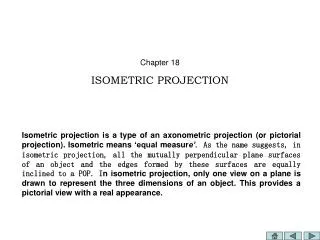
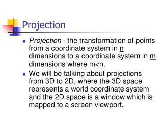
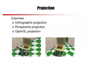
Types of Axonometric Projection • Isometric – has equal foreshortening along each of the three axis directions • Dimetric – has equal foreshortening along two axis directions and a different amount on the third axis • Trimetric – has different foreshortening along all three axis directions
Isometric Projection • The projections of the edges of a cube in isometric projection make angles of 120 degrees with each other
Isometric Projection • Lines of an isometric drawing that are not parallel to the isometric axes are called nonisometric lines • These lines are not equally foreshortened
Isometric Projection • Isometric scales can be used to draw correct isometric projections • All distances are approximately 80% of true size
Isometric Drawings • Isometric drawings, unlike isometric projections, are drawn using the full length measurements of the actual drawing and lacks foreshortening • The isometric drawing is about 25% larger than the isometric projection
Hidden Lines and Centerlines • Hidden lines are omitted unless they are needed to make the drawing clear • Center lines are shown if they are needed to indicate symmetry or if they are needed for dimensioning
Angles in Isometric • Angles project true size only when the plane containing the angle is parallel to the plane of projection • An angle may project to appear larger or smaller than the true angle depending on its position
Circles in Isometric • If a circle lies in a plane that is not parallel to the plane of projection, the circle projects as an ellipse • Ellipses can be constructed using offset measurements
Ellipses in Isometric • Approximate ellipses can be constructed from arcs
Screw Threads in Isometric • Parallel partial ellipses equally spaced at the symbolic thread pitch can be used to represent screw threads
Isometric Sectioning • Isometric sectioning is useful in drawing open or irregularly shaped objects
Isometric Dimensioning • Isometric dimensions are similar to dimensions on multiview drawings but should match the pictorial style
Sketch an Isometric Drawing Front view given should be the rear view of the Isometric Drawing Scale 1:4