Download
1 / 30
300 likes | 430 Vues
Pixel Support Tube and Related. November 9, 2001 Pixel Day E. Anderssen, LBNL. Overview. Status of Work, technical and other PST and Supports Pixel Supports Service/Beampipe Supports Immediate plans Prototyping in ‘02 Discrepancies All along the way…. +X. +Z. +Y Vertical.

E N D
Pixel Support Tube and Related November 9, 2001 Pixel Day E. Anderssen, LBNL
Overview • Status of Work, technical and other • PST and Supports • Pixel Supports • Service/Beampipe Supports • Immediate plans • Prototyping in ‘02 • Discrepancies • All along the way… E. Anderssen LBNL
+X +Z +Y Vertical Agreed Support Positions outside PST PST Support Conditions Under Investigation Chain of Support for PST to Cryostat Side C Side A ID Flat Rail View from top—all Tube Supports are Horizontal and Co-planar TRT SCT PIXEL SUPPORT TUBE Support Positions are shown, But constraint conditions are Not indicated here. ID Vee Rail Properties TBD Constraint TBD E. Anderssen LBNL
Support Conditions of Beampipe • Beampipe Cruciform Supports align with Stiffest part of PST—the end flanges • All support planes on frame are wires allowing longitudinal (axial) float • One Z-Fixture is foreseen to take up ATLAS Access/Opening loads E. Anderssen LBNL
Pixel Support Tube Mockup • Mockup in three pieces to simulate independent parts of tube • Goal is for full length of entire tube to simulate all installation scenarios • Detector rails are removable, should modification be necessary • Intend to run ‘installation tests’ in ‘02 E. Anderssen LBNL
Rail Design in Support Tube Vee and Flat rails were chosen to provide pseudo-kinematic support for the detector during delivery to the support points Rails are used only for delivery, not support mockup E. Anderssen LBNL
PST Important Features 10 45 End Support 30 Hoop Hat Stiffeners (section view) Bolt flanges End Supports Sct mount pads End Plugs (1 mm equiv. carbon sheet) E. Anderssen LBNL
Support Flange Bonded Assembly Old design - now gone for independent thermal barrier Flange Face (machined layup) Stiffeners (layups) T-nuts (bonded) Flange base (Layup) E. Anderssen LBNL
Slider design - materials testing • Friction Tester nearing completion • Applies variable pressure • Measures angular acceleration • Slides sample against interchangeable disk of given material Mass provides normal force position is movable along arm M arm hinge turntable (carbon disk) slider to be tested Encoder on shaft measures acceleration M E. Anderssen LBNL
Gravity Sag Calculations Carbon Glass DY = .57 mm DY = 1.6 mm Whole Tube Sags at ends during operation—it is intended to ‘remove’ this sag when Reattaching supports after installation of Forward ID Note: Sag is with Package in place—much less without E. Anderssen LBNL
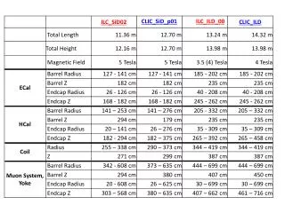
Model Material Both Ends Bent – 1 Z Constraint FX (N) FY (N) FZ (N) MX (Nm) MY (Nm) MZ (Nm) Model Material FX (N) FY (N) FZ (N) MX (Nm) MY (Nm) MZ (Nm) Carbon - 151 0 253 - - Carbon 146 - - - 233 - Glass - 53 0 89 - - Glass 52 - - - 83 - Both Ends Bent – 2 Z Constraints Model Material FX (N) FY (N) FZ (N) MX (Nm) MY (Nm) MZ (Nm) Carbon 297 - 1870 - 536 - Glass 108 - 468 - 110 - One End Bent – 1 Z Constraint Model Material FX (N) FY (N) FZ (N) MX (Nm) MY (Nm) MZ (Nm) Carbon 390 - - - 623 - Glass 137 - - - 218 - Reaction Loads On SCT Vertical Bending – Both Ends Horizontal Bending E. Anderssen LBNL
Fy My Fz Mz Fx Mx Flexure Block interface to SCT Penetration SCT Thermal Barrier Penetration This interface must take same loads as applied to Flexure—Will know them well after Joint Model is run Will look at simple feasibility with current (infinite stiffness) loads Will iterate size if indicated by ROM calculation E. Anderssen LBNL
Flange Envelope May change By ~5mm to 806new structure added Interlink 796800 785792 811 775780 806 SCT BARREL 3 765 SCT Forward Envelope 261 260 257259.5 251 requested Changes 248 245246 242 244 240 Barrel Mount Flange Pixel Support Tube (Barrel Region) Pixel Support Tube (forward) 700 795799 Dimensions from 1:1 ID Layout May ‘01 E. Anderssen LBNL
Flange Envelope Interlink 800 811 806 792 SCT BARREL 3 780 765 SCT Forward Envelope 261 260 255 252 251 shim 254 246 shim 242 244 240 Barrel Mount Flange Pixel Support Tube (Barrel Region) Pixel Support Tube (forward) 700 799 New Proposed Envelopes—not yet agreed E. Anderssen LBNL
Z-Flexure (Side A) View Direction Thermal Barrier squeezed in here Metal Insert Bonded in Cut Plane Access hole Thru Service Rail Dowel pins have line fit Insulator (G10) or Al203 Gap filled After picture Support Tube Mount Pad M55J E. Anderssen LBNL
Pixel Supports E. Anderssen LBNL
Service and Beampipe Support Service and Beampipe Support Pixel Package Assembly Mockup Pixel Frame shown E. Anderssen LBNL
Tension/Compression Transmission through structures not services Clips register to Buttons on Frame and Service/Beampipe support structure Gaps allow ‘Phi’ offsets of up to +/- 1mm while only 0.25mm longitudinally E. Anderssen LBNL
Wire Planes supported by Pulleys Wires not modeled, beampipe not shown E. Anderssen LBNL
Tubes route cables to BarrelSeparate blocks at Forward end E. Anderssen LBNL
Services Supported By Framework E. Anderssen LBNL
Service quarter panels supported by framework E. Anderssen LBNL
Need to adjust length of Tube or Support Plane location of VI E. Anderssen LBNL
Outside view of patch Panel E. Anderssen LBNL
Section View of patch Panel E. Anderssen LBNL
Barrel End of Support Structure E. Anderssen LBNL
PST Prototyping Plans • Short Mandrel • 1 foot long - 1 for glass, 1 for carbon – aluminum or steel • “Dry-run” in autoclave to determine thermal response • Determine final diameters from test layups • Full Size Mandrel (forward length) • Quotes already received • Approximately 14,000 to 20,000 USD • 8 Weeks delivery • Plans to Fabricate forward prototype in glass • All flanges and rail features • Use for production forwards if diameters are correct • Implications of Glass Forwards/Carbon Barrel on prototyping plans must be more fully assessed • Insertion Testing E. Anderssen LBNL
PST Prototypes in ETC ‘02 • Includes • Friction Testing • Material Test Panels • “Foot Long” prototypes • End-Plug Prototype estimated as ½ production total • Gray area • Calling first Forward Tube a prototype—Production monies all in FY’03, but need to order tooling and start fab in ’02 • Missing prototype flexure mounts (as noted in 1.1.1.1.3.5) • Prototype ‘End Plate’ buried in Frame estimate, but included Pixel mounts (~$5k ’01, $10k ’02) • Monies for assembly testing of Insertion mockup spread over a few efforts and called ‘testing’ hard to track if appropriate levels have been assigned E. Anderssen LBNL
Service Support Prototypes ‘02 • Now includes Beam Vacuum Support Structure • Prototype in ’02 already includes bond fixture—need to increase cost some to account for additional scope of VI support, but this saves overall by not having entire extra fixture for VI support • Intention for ’02 to build 1 quarter panel support and 2 service panels—still valid • Need to build Full VI support for both installation testing and to support services • Needs to be ‘real’ for use in case pixels are late • Needs to have ‘real’ rail interface (unless replaceable interface) • Need to add cost to this section of WBS, or make new WBS for Beam pipe support E. Anderssen LBNL
Recent Changes and Estimate of Impact • Change of Forwards to Quartz fiber— +$30k • Additional Shell tool $14-20k • Additional Hat stiffeners ~120-160 Man hours M-tech • Introduction of Independent SCT Thermal Barrier +$35k • Throw away ~3-4 man months LBL/Junior Eng Design time • Accrue additional 2-3 man months re-design of Flange/Flexures • Increase in scope to include Beam Vacuum Supports +$110k • Design time not assessed • Attempt to use/re-use as much fixture costs as possible • Estimate ~$25k Material/200hr Shop/300hr M-tech (REAL) ‘03 • Estimate ~$10k Material/200hr Shop/300hr M-tech (prototype) ’02 • (Est. based on cost of End Plug and fixturing, using same tool as service panel support structure • PST End Support (former Beam Vacuum Support) not included in cost estimates yet. • PPI/Endplug Thermal barrier increase in Complexity • Current Estimate based on segmented flat panel. Cost will increase if tool is needed to make other than a flat shape. E. Anderssen LBNL