Download
1 / 19
190 likes | 342 Vues
A Projective Framework for Radiometric Image Analysis. CVPR 2009 Date: 2010/3/9 Reporter : A nnie lin. Image reflectance . Image reflectance : diffuse reflectance + specular reflectance . How to estimate shape from images?. 1. shape from shading – add more constrain

E N D
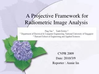
A Projective Framework for Radiometric Image Analysis CVPR 2009 Date: 2010/3/9 Reporter : Annie lin
Image reflectance Image reflectance : diffuse reflectance + specular reflectance
How to estimate shape from images? 1. shape from shading – add more constrain 2. photometric stereo – take more images -> get “normal field” butGBR (Generalize bas-Relief) ambiguity the same image can be produced by different surface under corresponding lighting direction. - GBR Transformation Shape: “depth scaling” and ‘additive plane’
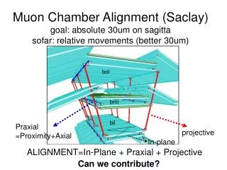
Specular reflectance and GBR • GBR is resolved by ‘almost any’ additive specular reflectance component. • Only requirements • Spatially uniform • Isotropic • Reciprocal Isotropy + reciprocity: • Local light/view directions equivalent at distinct points • Observed reflectance equal
Outline • Reflectance symmetries on the plane • Isotropic and reciprocal • Isotropic-reciprocal quadrilateral • GBR Transformation • Reconstruction via photometric stereo and show how to resolve shape ambiguities in both “uncalibrated ” and “calibrated ” cases • Applications • Uncalibrated photometric stereo • Calibrated photometric stereo • Conclusion
Reflectance symmetries on the plane • The real projective plane provides and effective tool for analyzing reflectance symmetries , of which we focus on reciprocity and isotropy in this paper
Isotropic Pair form an isotropic pair with respect to , if Gauss sphere
Isotropic Curve and Symmetry Isotropic curve: Gauss sphere, top view • Union of isotropic pairs • Radiance function is symmetric
Reciprocal Pair equal BRDF value form an reciprocal pair with respect to if Gauss sphere
Reciprocal Curve & Symmetry Reciprocal curve Gauss sphere, top view • Union of reciprocal pairs • BRDF symmetry along curve
Transformation • Reconstruction via photometric stereo and show how to resolve shape ambiguities in both “uncalibrated ” and “calibrated ” cases • Linear transformations of the normal field correspond to projective transformations of the loane , so now disscusses the behavior of our symmetry-induced structure under projective tranformations
Propositions • Proposition 1. • A rotation (about the origin) and a uniform scaling are the only linear transformations that preserve isotropic pairs with respect to two or more lighting directions that are non-coplanar with the view direction. • Proposition 2. • If the principal meridian vs is known, a classic bas-relief transformation is the only linear transformation that preserves isotropic pairs with respect to two or more sources that are non-collinear with the view direction • Proposition 3. • If the lighting directions are known, theidentity transformation is the only linear transformation thatpreserves isotropic-reciprocal quadrilaterals with respect to • two or more lighting directions that are non-collinear withthe view direction.
Application : uncalibrated photometric stereo • GBR transformation affects the normals and source directions • A GBR transformation scales and translates the quadrilateral to and moves the source to a different point ¯s on the principal meridian • To resolve the GBR ambiguity, we must find the transformation that maps back to its canonical position. • Proposition 4. • The GBR ambiguity is resolved by the isotropy and reciprocity constraints in a single image.
By isotropy and reciprocity, an isotropic-reciprocal quadrilateral (n,m, n′,m′) with respect to s, satisfies: • Using (6)(7) A hypothesis (′ v1, λ1) yields hypotheses for the point h × (v × s) and BRDF value at each point. These in turn induce a hypothesis for the reciprocal match ¯m as the intersection of the iso-BRDF curve and the join of n and the hypothesized h×(v×s) provides a measure of inconsistency, and the exhaustive 2D search is used to minimize this inconsistency.
calibrated photometric stereo • Given a set of images I(x, y, t) captured using a cone of known source directions s(t), t ∈ [0, 2) centered about view direction v, this method yields one component of the normal at every image point (x, y). • if the surface is differentiable, the surface gradient direction can be recovered at each point, but the gradient magnitude is unknown. This means that one can recover the ‘iso-depth contours’ of the surface, but that these curves cannot be ordered • Consider a surface S = {x, y, z(x, y)} that is described by a height field z(x, y) on the image plane. A surface point with gradient zx, zy is mapped via the Gaussian sphere to point n ≃ (zx, zy,−1) in the projective plane, and the ambiguity in gradient magnitude from[1] corresponds to a transformation of normal field ¯n(x, y) ≃ diag(1, 1, (x, y))n(x, y), where the per-pixel scaling λ (x, y) is unknown
Proposition 5. • In the general case, if differentiable height fields z1(x, y) and z2 = h(z1) are related by a differentiable function h and possess equivalent sets of iso-slope contours, the function h is linear • If the surface has uniform reflectance (or has a uniform separable component), the match ¯n′ can be located by intersecting this line with the iso-intensity contour passing through ¯n. Such isotropic matches ¯n′(t) under all light • directions s(t), t ∈ [0, 2) define the iso-slope contour • if the spatially varying BRDF is of the form in Eq. (8), a necessary condition • for two points (x1, y1) and (x2, y2) to have normal directions forming an isotropic pair is In(x1, y1, t) = In(x2, y2, t) ∀ t ∈ [0, 2). • This is because normalizing the temporal radiance at each pixel to [0, 1] removes the effects of the spatially-varying reflectance terms f1 and f2.


![Geoneutrino Radiometric Analysis For Geosciences [GRAFG]](https://cdn2.slideserve.com/4382941/slide1-dt.jpg)