Unit 12 Oil Heat Components
140 likes | 333 Vues
Unit 12 Oil Heat Components. OBJECTIVES. After studying this Unit, the reader should be able to. List and describe the parts of a high pressure oil burner Describe service procedures for oil burner components. GUN-TYPE OIL BURNER. Oil and air forced into burner for mixing and ignition

Unit 12 Oil Heat Components
E N D
Presentation Transcript
OBJECTIVES After studying this Unit, the reader should be able to • List and describe the parts of a high pressure oil burner • Describe service procedures for oil burner components
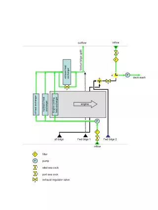
GUN-TYPE OIL BURNER • Oil and air forced into burner for mixing and ignition • Burner motor provides power for the fan and fuel pump • Burner fan or blower – Forces air into the chamber • Fuel oil pumps – delivers oil to the chamber • Nozzle – atomizes oil prior to ignition • Air tube – delivers air to the chamber • Electrodes – provides spark for ignition • Ignition transformer / electronic igniters • Primary control unit – controls burner operation
Transformer Motor Blower Nozzle Air Inlet Collar Flexible Coupler Air Tube Electrodes Fuel Pump Mounting Flange Static Disc End Cone Blower Housing OIL BURNER COMPONENT PARTS
BURNER MOTOR • Split-phase fraction horsepower motor • Facilitates motion of the blower and fuel pump • Flexible coupler connects motor to the pump • Normal motor speeds are 1750 and 3450 rpm • Pump should always match the pump’s rpm
BURNER FAN OR BLOWER • Squirrel cage blower • Has an adjustable air inlet opening • Fan forces air through the air tube to the combustion chamber • The air is mixed with atomized fuel in preparation for combustion
FUEL OIL PUMPS • Can be either single or two-stage pumps • Pump has a built in pressure regulator • Pressure regulator can be adjusted • Oil pressures range from 100 psig to 140 psig • Single stage pumps are used when the oil tank is located above the burner • Two-stage pumps are used when oilis stored below the burner
NOZZLES • Atomizes the fuel for combustion • Bore size determines the amount of oil used • Rated by spray pattern, flow rate and angle • Spray patterns: hollow, solid, or semi-solid cones • Flow rate is measured in gallons per hour • Spray angles range from 30 to 90 degrees • Always select the proper nozzle
Orifice Stainless Steel Orifice Disc Stainless Steel Distributor Brass Body Screwpin Sintered Filter THE NOZZLE
ELECTRODES • Located within the air tube • Metal rods insulated with ceramic insulators • Electrode ends make contact with the transformer terminals • Provide a high voltage spark for ignition • Continuous or intermittent ignition
Air Tube Static Disc Electrodes Ceramic Insulators End Cone Nozzle
IGNITION TRANSFORMERS & ELECTRONIC IGNITERS • Step-up transformers with 120-volt primary • Secondary voltage is 10,000 volts or more • Provides the high voltage to the electrodes • Cannot be serviced in the field • Spark can be checked in the field
HEAT EXCHANGER • Exchangers transfer the heat from combustion to the air that is circulated to heat the structure • Heat exchangers also separate flue gases from the air circulated to heat the structure • Heat exchangers should be inspected during normal service for cracks • Some states allow cracked heat exchangers to be welded, but most do not • Correct airflow is important across the heat exchanger
Unit Summary • The typical oil burner contains a motor, blower, fuel pump, nozzle, electrodes and primary control • Nozzles rated by flow rate, angle and spray pattern • Ignition transformers and electronic igniters provide the high voltage needed for spark ignition