Engineering Mechanics: Statics
Engineering Mechanics: Statics. Chapter 4: Structures. Statically Determinate Structure. Do not have more supporting constraints than are necessary to maintain equilibrium This chapter focus on trusses, frames and machines

Engineering Mechanics: Statics
E N D
Presentation Transcript
Engineering Mechanics: Statics Chapter 4: Structures
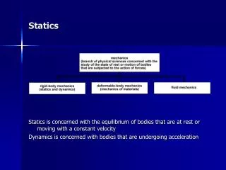
Statically Determinate Structure Do not have more supporting constraints than are necessary to maintain equilibrium This chapter focus on trusses, frames and machines Truss = A framework composed of members joined at their ends to form a rigid structure When the members lie in a single plane = a plane truss
Simple Trusses Basic element of a plane truss = triangle Three bars joined by pins at their ends constitute a “rigid” frame (noncollapsible) Structures built from a basic triangle are known as simple trusses Truss members = Two-force members
Simple Trusses Assumptions All external forces are applied at the joints. (If consider weight, apply half of the magnitude at each end) The members are joined together by pin connections Two approaches for force analysis Method of joints Method of sections
Method of Joints Used to find the forces in the truss members Analysis steps Draw FBD of a joint Use and to find the member forces Begin analysis with a joint where at least one known load exists Not more than two unknown forces are present
Method of Joints • Special conditions • Zero-force member (a) Three members – two collinear + one noncollinear (b) Two noncollinear members • Two pairs of collinear members – forces in each pair equal and opposite • Choice of reference axis
Problem 4/20 A snow load transfers the forces shown to the upper joints of a Howe roof truss. Neglect any horizontal reactions at the supports and solve for the forces in all members Problem 4/21
Method of Sections Take advantage of moment equation of equilibrium Not necessary to proceed with the calculation from joint to joint until the member in question has been reached Procedures 1. Determine external reactions by considering whole truss (R1 & R2) 2. An imaginary section (dashed line) is passed through the truss 3. To determine BC use To determine FE use To determine BE use
Sample Problem 4/4 Calculate the force in member CD and member DJ of the roof truss illustrated. Neglect any Horizontal components of force at the supports
Structures which contain one or more multi-force members Frame = Structure designed to support loads Machine = Structure which transforms input actions (forces or couples) to output actions Frames and Machines
Determine the force supported by the roller at E. AnsE = 150 N Problem 4/71
The elements of a floor jack are shown in the figure. The figure CDFE is a parallelogram. Calculate the force in the hydraulic cylinder AB corresponding to the 10-kN load supported as shown. What is the force in link EF? Problem 4/80