Construction Dewatering
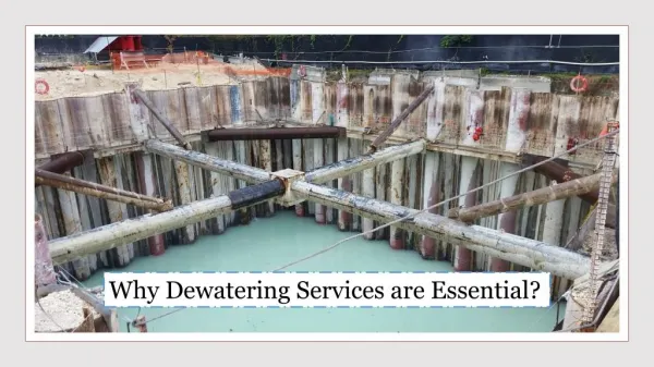
Construction Dewatering. Lecture 11. Construction Dewatering. The purpose of construction dewatering is to control the surface and subsurface hydrologic environment in such a way as to permit the structure to be constructed “ in the dry .”

Construction Dewatering
E N D
Presentation Transcript
Construction Dewatering Lecture 11
Construction Dewatering • The purpose of construction dewatering is to control the surface and subsurface hydrologic environment in such a way as to permit the structure to be constructed “in the dry.” • Dewatering means “the separation of water from the soil,” or perhaps “taking the water out of the particular construction problem completely.” • This leads to concepts like pre-drainage of soil, control of ground water, and even the improvement of physical properties of soil.
Dewatering: CAISSONS • Excavation from within the permanent structure. • If the site is on land, the structure is built in place. • If the site is offshore, the structure is floated into position. • To reduce the frictional resistance between the caisson and the surrounding ground: • Add weight • Bentonite clay slurry is injected at the soil-structure interface. • Jetting is used in cohesionless soils.
CAISSONS (Cont’d) • During unwatering a caisson in cohesionless soils, the upward flow from the surrounding groundwater induces a quick condition which results in loss of strength at the bottom of excavation. • To prevent quick condition, the head difference causing flow should be kept low. • Caissons should not be used in the vicinity of existing structures that can be damaged due to loss of ground from beneath their foundations.
Permeability and SeepageFlow of Water in Soil • Soils have interconnected voids through which water can flow from points of high energy to points of low energy. • It is necessary to estimate the quantity of underground seepage for investigating problems involving the pumping of water for underground construction, and making stability analysis of earth dams and earth-retaining structures that are subjected to seepage forces.
Permeability Test(Constant Head Test) • ASTM D2434 • q = Water flowing through the soil at a constant rate • Q = Amount of water collected in a given time period, t • Then:Q = qt • Apparent velocity of the flow Soil area,A q H L Q or
Permeability (Cont’d) • In 1856, Darcy published a simple equation for the discharge velocity of water through saturated soils: • n: the apparent velocity • k: the coefficient of permeability (aka:Hydraulic conductivitya material’s constant) • i: hydraulic gradient • By definition: • H : the head causing flow over the distance L.
Permeability (Cont’d) Q = qt => Q = (vA)t => Q = (ki) At Q = k ( ) At Solve fork:
Range of Permeability for Various Soils • Gravels are 1 million times more pervious than clays
Example for the Constant Head Test • For a constant head laboratory permeability test on a fine sand, the following values are given: • Length of specimen = 10 in. • Diameter of specimen = 2.5 in. • Head difference = 18 in. • Water collected in 2 minutes = 0.031 in.3 • Determine: a. Hydraulic conductivity, k, of the soil (in./min.) b. Discharge velocity
Permeability in the Fieldby Pumping from Wells • In the field, the average hydraulic conductivity of a soil deposit in the direction of flow can be determined by performing pumping tests from the well.
k Determined from Pumping Tests For D10 = 0.3 mm, k = 2000x10-4 cm/sec = 0.2 cm/sec 0.3
Example • Consider the case of pumping from a well in an unconfined permeable layer underlain by an impermeable stratum. Given: • q = 26 ft3/min • H1 = 15.7 ft at R1 = 100 ft • H2 = 18.0 ft at R2 = 200 ft • Calculate the hydraulic conductivity (in ft/min) of the permeable layer.
Dewatering Methods - Wellpoints • Small pipes, up to 2.5 inches in diameter, connected to screens at the bottom and to a vacuum header pipe at the surface constitute a wellpoint system.
Dewatering Methods - Wellpoints • Effective lifts of 15 ft. are quite common at sea level, and under certain circumstances, lifts can be increased to as much as 25 ft. • Effective lifts of 15 ft. are quite common at sea level, and under certain circumstances, lifts can be increased to as much as 25 ft.
Dewatering Methods - Wellpoints Multistage wellpoint system