Lecture - 8 First order circuits
Lecture - 8 First order circuits. Outline. First order circuits. The Natural Response of an RL Circuit. The Natural Response of an RC Circuit. The Step Response of RL Circuits. The Step Response of RC Circuits. A General Solution for Step and Natural Responses.

Lecture - 8 First order circuits
E N D
Presentation Transcript
Outline • First order circuits. • The Natural Response of an RL Circuit. • The Natural Response of an RC Circuit. • The Step Response of RL Circuits. • The Step Response of RC Circuits. • A General Solution for Step and Natural Responses.
First order circuits • A first-order circuit may be reduced to a Theveninequivalent connected to either a single equivalent inductor or capacitor.
The Natural Response of an RL Circuit • We assume that the independent current source generates a constant current and that the switch has been in aclosed position for a long time. • Thus only constant, or dc, currents can exist in the circuit just prior to the switch's being opened, and therefore the inductor appears as a short circuit (Ldi/dt = 0) prior to the release of the stored energy. Therefore, all the source current appears in the inductive branch • Finding the natural response requires finding the voltage and current at the terminals of the resistor after the switch has been opened, that is, after the source has been disconnected and the inductor begins releasing energy. The circuit for t ≥ 0
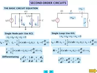
The Natural Response of an RL Circuit • To find i(t), we use Kirchhoff s voltage law to obtain an expression involving i, R, and L. Summing the voltages around the closed loop gives: • which shows that the current starts from an initial value I0 and decreases exponentially toward zero as t increases. Solving
The Natural Response of an RL Circuit • The coefficient of t—namely, R/L—determines the rate at which the current or voltage approaches zero. The reciprocal of this ratio is the time constant of the circuit, denoted τ= L/R • The time constant of an RL circuit equals the equivalent inductance divided by the Thevenin resistance as viewed from the terminals of the equivalent inductor. • Calculating the natural response of an RL circuit can be summarized as follows: 1. Find the initial current, I0, through the inductor. 2. Find the time constant of the circuit, τ= L/R. 3. Use Eq. I0 e-t/τ, to generate i(t).
The Natural Response of an RC Circuit • We assume that the independent current source generates a constant current and that the switch has been in aclosed position for a long time. • Thus only constant, or dc, currents can exist in the circuit just prior to the switch's being opened, and therefore the capacitor appears as a open circuit (Cdv/dt = 0) prior to the release of the stored energy. Therefore, all the source voltage appears across the capacitor terminal. • Finding the natural response requires finding the voltage and current at the terminals of the resistor after the switch has been opened, that is, after the source has been disconnected and the capacitor begins releasing energy. The circuit for t ≥ 0
The Natural Response of an RC Circuit • To find v(t), we use Kirchhoff s current law to obtain an expression involving v, R, and C. Summing the currents away from the upper junction between R and C gives gives: • which shows that the voltage starts from an initial value V0 and decreases exponentially toward zero as t increases. Solving
The Natural Response of an RC Circuit • The coefficient of t—namely, 1/RC—determines the rate at which the current or voltage approaches zero. The reciprocal of this ratio is the time constant of the circuit, denoted τ= RC • The time constant of an RC circuit equals the equivalent capacitance times the Thevenin resistance as viewed from the terminals of the equivalent capacitor. • Calculating the natural response of an RC circuit can be summarized as follows: 1. Find the initial voltage, V0, across the capacitor. 2. Find the time constant of the circuit, τ = RC. 3. Use Eq. v(t) = V0e-t/ τ, to generate v(t).
The Step Response of RL Circuits • Step response: finding the currents and voltages generated in first-order RL or RC circuits when either dc voltage or current sources are suddenly applied. • The task is to find the expressions for the current in the circuit and for the voltage across the inductor after the switch has been closed. • After the switch in circuit has been closed, Kirchhoff s voltage law requires that: Solving
The Step Response of RL Circuits • Which indicates that after the switch has been closed, the current increases exponentially from zero to a final value of Vs/R. • The time constant of the circuit, L/R, determines the rate of increase. • The voltage across an inductor is Ldi/dt, so: • If the initial current is zero, the voltage across the inductor jumps to Vs. We also expect the inductor voltage to approach zero as t increases, because the current in the circuit is approaching the constant value of Vs/R.
The Step Response of RC Circuits • The task is to find the expressions for the current in the circuit and for the voltage across the capacitor after the switch has been closed. • After the switch in circuit has been closed, Kirchhoff s current law requires that: Solving
The Step Response of RC Circuits • Which indicates that after the switch has been closed, the voltage increases exponentially from zero to a final value of IsR. • The time constant of the circuit, RC, determines the rate of increase. • The current in an capacitor is Cdv/dt, so: • If the initial voltage is zero, the current in the capacitor jumps to Is. We also expect the capacitor current to approach zero as t increases, because the voltage in the circuit is approaching the constant value of IsR.
A General Solution for Step and Natural Responses • The general solution for natural and step responses of RL and RC circuits is: • Therefore, when computing the step and natural responses of circuits, it may help to follow these steps: 1. Identify the variable of interest for the circuit. For RC circuits, it is most convenient to choose the capacitive voltage; for RL circuits, it is best to choose the inductive current. 2. Determine the initial value of the variable, which is its value at t0. 3. Calculate the final value of the variable, which is its value as t ∞. 4. Calculate the time constant for the circuit.
Example 3 • Assume that the switch in the circuit shown has been in position b for a long time, and at t = 0 it moves to position a. Find: (a) i(0+); (b) v(0+); (c) τ,t > 0; (d) i(t), t > 0; (e) v(t), t > 0+.
Example 4 • The switch in the circuit shown in circuit shown has been closed a long time before opening at t = 0. For t ≥ 0+, find a) v0(t). b) i0(t). c) i1(t). d) i2(t) e) i1(0+).
Summary • A first-order circuit may be reduced to a Thevenin (or Norton) equivalent connected to either a single equivalent inductor or capacitor. • The natural response is the currents and voltages that exist when stored energy is released to a circuit that contains no independent sources. • The time constant of an RL circuit equals the equivalent inductance divided by the Thevenin resistance as viewed from the terminals of the equivalent inductor. • The time constant of an RC circuit equals the equivalent capacitance times the Thevenin resistance as viewed from the terminals of the equivalent capacitor.
Summary • The step response is the currents and voltages that result from abrupt changes in dc sources connected to a circuit. Stored energy may or may not be present at the time the abrupt changes take place. • The solution for either the natural or step response of both RL and RC circuits involves finding the initial and final value of the current or voltage of interest and the time constant of the circuit.