Chromatic Aberration
Chromatic Aberration. The thin lens equation was derived using Snell’s Law , which was derived using the wave theory’s explanation of refraction.

Chromatic Aberration
E N D
Presentation Transcript
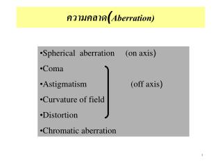
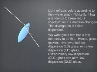
Chromatic Aberration • The thin lens equation was derived using Snell’s Law, which was derived using the wave theory’s explanation of refraction. • The wave theory’s explanation of color is based on frequency and wavelength. We can explain dispersion (rainbow and prism) by using the wave theory’s explanation of different colors having different speeds and hence different indices of refraction for the same material.
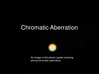
Chromatic Aberration • Putting these two ideas together, we come up with the prediction that the focal length of lenses will be slightly different for different colors! • This means that a single lens will not be able to focus white light perfectly. We actually observe this, and it is called Chromatic Aberration. • To reduce this, we can employ two lenses with different materials to replace a single lens. This adds to the expense and is one reason why good cameras are so expensive.
Waves So far, the wave theory has explained things very well: • speed of light • different colors • reflection • refraction (dispersion, thin lenses) To look at the next property, shadows, we need to review the wave idea a little bit.
Waves (in general) Sine waves are “nice”. Other types of waves (such as square waves, sawtooth waves, etc.) can be formed by a superposition of sine waves - this is called Fourier Series. This means that sine waves can be considered as fundamental.
Waves (in general) E = Eosin()where is a phase angle which describes the location along the wave = 90 degrees is the crest =270 degrees is the trough
Waves (in general) E = Eosin() where is a phase angle in a moving wave, changes with both • time (goes2radians in time T) and • distance (goes 2radians in distance ) so = (2/)*x +/- (2/T)*t • where2/T = and • where 2/ = kand so phase speed: v = distance/time = /T = f =/k
Waves (in general) For nice sine waves: E = Eo sin(kx +/- t) For waves in general, we can break the wave into component sine waves; this is called spectral analysis.
Property #5: Light and Shadows Consider what we would expect from particletheory: sharp shadows dark dark light
Light and Shadows Consider what we would expect from wave theory: shadows NOT sharp crest crest crest dark dark dim light dim
Light and Shadows What DOES happen? Look at a very bright laser beam going through a vertical slit. (A laser has one frequency unlike white light.)
Double Slit Experiment We will consider this situation but only after we consider another: the DOUBLE SLIT experiment: note: the different colors are used only to distinguish between the light that goes through the different slits. It should not be interpreted to mean that different colors of light go through the different slits.
Double Slit Experiment Note that along the solid green lines are places where crests meets crests and troughs meet troughs. crest on crest followed by trough on trough
Double Slit Experiment Note that along the dotted lines are places where crests meets troughs and troughs meet crests. crest on trough followed by trough on crest crest on crest followed By trough on trough
Double Slit Experiment Further explanations are in the Introduction to the Computer Homework Assignment Vol 5 #3 on Young’s Double Slit. crest on trough followed by trough on crest crest on crest followed By trough on trough
Double Slit Experiment Our question now is: How is the pattern of bright and dark areas related to the parameters of the situation: , d, x and L? bright x dim d bright dim L bright SCREEN
Double Slit Experiment Magnified view of the slit and the direction of the light to the first (not central) maximum: sin() = / d purple angles 90o note: requires < d d
Double Slit Experiment Magnified view of the slit and the direction of the light to the first (not central) maximum: sin() = / d purple angles 90o note: requires < d d
Double slit: an example n = d sin(n) d tan(n) = d (xn / L) d = 0.15 mm = 1.5 x 10⁻⁴ m x = ??? measured in class L = ??? measured in class n = 1 (if x measured between adjacent bright spots) = d x / L = (you do the calculation)
Interference: Diffraction Grating The same Young’s formula works for multiple slits as it did for 2 slits. lens bright s1 s2 s3 s2 = s1 + s3 = s2 + = s1 + 2 s4 = s3 + = s1 + 3 s5 = s4 + = s1 + 4 d bright s4 s5 4
Interference: Diffraction Grating With multiple slits, get MORE LIGHT and get sharper bright spots. lens bright s1 s2 s3 s2 = s1 + s3 = s2 + = s1 + 2 s4 = s3 + = s1 + 3 s5 = s4 + = s1 + 4 d bright s4 s5 4
Interference: Diffraction Grating With 5 slits, get cancellation when s = 0.8; with two slits, only get complete cancellation when s = 0.5 . lens bright dark s1 s2 s3 s2 = s1 + .8 s3 = s2 + .8 = s1 + 1.6 s4 = s3 + .8 = s1 + 2.4 s5 = s4 + .8 = s1 + 3.2 d bright s4 s5 3.2
Colors and Wavelengths for visible light, using the diffraction grating, we come up with the following: • violet 400 - 450 nm • blue 450 - 500 nm • green 500 - 550 nm • yellow 550 - 600 nm • orange 600 - 650 nm • red 650 - 700 nm
Colors and wavelengths The wavelengths specified for the colors on the previous slide are only approximate, and they do vary slightly with each person. On any test, I will give you one color leeway, e.g., if the wavelength falls in the green range (previous slide), but you answer either blue or yellow, I will count your answer correct. Is the way we see different wavelengths (frequencies) of light similar to the way we hear different frequencies of sound?
Sound and frequencies For sound, our ears function like a Fourier analyzer – we can actually hear each frequency. If we mix frequencies, we hear a chord. We can distinguish the base from the treble; we can distinguish the guitar from the piano.
Colors and frequencies For light, our eyes do NOT act this way. If we mix frequencies, we see only one color which is different from either of the “pure” colors (frequencies). We have two different types of retinal cells: rods and cones. The rod cells are not that closely packed, and only send a black and white signal. There are three different types of cone cells which act as color light receptors. The next slide shows only a rough picture. You should look at more advanced texts to get a more accurate picture.
Cone cells Cone cell sensitivity to different wavelengths 400 450 500 550 600 650 700 (in nm) If only the “blue” cone is activated, the color is violet. If both the “blue” and “green” cones are activated, and the “blue” gives a stronger signal, the color is blue. If both the “blue” and “green” cones are activated, and the “green” gives a stronger signal, the color is green.
Cone cells Cone cell sensitivity to different wavelengths 400 450 500 550 600 650 700 (in nm) If both the “green” and “red” cones are activated, and the “green” gives a stronger signal, the color is yellow. If both the “green” and “red” cones are activated, and the “red” gives a stronger signal, the color is orange. If only the “red” cone is activated, the color is red.
Colors and Wavelengths For other types of light (based on the technology used to make the light): • radio: f is 1MHz for AM, 100 MHz for FM so is 1 km to 10 cm • microwaves/radar: 10 cm to 1 mm • infrared: 1 mm to 700 nm • visible 700 nm to 400 nm • ultraviolet 400 nm to 10 nm • x-ray & ray 10 nm on down
Diffraction: single slit How can we explain the pattern from light going through a single slit? screen x w L
Diffraction: single slit If we break up the single slit into a top half and a bottom half, then we can consider the interference between the two halves. screen x w L
Diffraction: single slit The path difference between the top half and the bottom half must be /2 to get a minimum. screen x w L
Diffraction: single slit This is just like the double slit case, except the distance between the “slits” is w/2, and this is the case for minimum: (w/2) sin() = /2 screen x w L
Diffraction: single slit In fact, we can break the beam up into 2n pieces since pieces will cancel in pairs. This leads to: (w/2n) sin(n) = /2 , or w sin(n) = nfor MINIMUM. screen x w L
Diffraction: single slit -2 -1 0 1 2 REVIEW: • For double (and multiple) slits: n = d sin(n) for MAXIMUM (for ALL n) • For single slit: n = w sin(n)for MINIMUM (for all n EXCEPT 0) -2 -1 0 1 2
Diffraction: single slit NOTES: • For double slit, bright spots are equally separated. • For single slit, central bright spot is larger because n=0 is NOT a dark spot. • To have an appreciable , d and w must be about the same size as & a little larger than • Recall that for small angles, sin) tan() = x/L
Diffraction: circular opening If instead of a single SLIT, we have a CIRCULAR opening, the change in geometry makes: the single slit pattern into a series of rings; and the formula to be: 1.22 n = D sin(n). The computer homework program on Resolution, CH Vol 5 #4 shows the rings in several diagrams and the use of this equation.
Diffraction: circular opening Since the light seems to act like a wave and spreads out behind a circular opening, and since the eye (and a camera and a telescope and a microscope, etc.) has a circular opening, the light from two closely spaced objects will tend to overlap. This will hamper our ability to resolve the light (that is, it will hamper our ability to see clearly).
Diffraction: circular opening How close can two points of light be to still be resolved as two distinct light points instead of one? One standard, called the Rayleigh Criterion, is that the lights can just be resolved when the angle of separation is the same as the angle of the first dark ring of the diffraction pattern of one of the points: limit = 1from 1.22 * = D sin(1) .
Rayleigh Criterion: a picture The lens will focus the light to a fuzzy DOT rather than a true point. lens D
Rayleigh Criterion: a picture The Rayleigh minimum angle, limit = sin-1(1.22 /D) = tan-1(x’/s’). lens D x’ s’
Rayleigh Criterion: a picture If a second point of light makes an angle of limit with the first point, (blue angle = green angle) then it can just be resolved. lens D x x’ s’ s
Rayleigh Criterion: a picture In this case: limit = sin-1(1.22 /D) = tan-1(x’/s’) = tan-1(x/s) . lens D x x’ s’ s
Rayleigh Criterion: an example • Consider the (ideal) resolving ability of the eye • Estimate D, the diameter of the pupil • Use = 550 nm (middle of visible spectrum) • Now calculate the minimum angle the eye can resolve. • Now calculate how far apart two points of light can be if they are 5 meters away.
Rayleigh Criterion: an example with D = 5 mm and = 550 nm, limit = sin-1 (1.22 x 5.5 x 10-7 m/.005 m) = 7.7 x 10⁻³ degrees = .46 arc minutes so x/L = tan(limit), and x = 5m * tan(7.7 x 10⁻³ degrees) = .67 mm
Rayleigh Criterion: an example • Estimate how far it is from the lens of the eye to the retinal cells on the back of the eye. • With your same D and and so same limit), now calculate how far the centers of the two dots of light on the retina are. • How does this distance compare to the distance between retinal cells (approx. diameter of the cells)?
Rayleigh Criterion: an example • L = 2 cm (estimation of distance from lens to retinal cells) • from previous part, limit = 7.7 x 10⁻³ degrees • so x = 2 cm * tan(7.7 x 10⁻³ degrees) = 2.7 m .
Limits on Resolution: • Imperfections in the eye (correctable with glasses) • Rayleigh Criterion due to wavelength of visible light • Graininess of retinal cells (Note that in low light where only the rods are activated, we cannot resolve very well because the rod cells are not packed as closely as the cone cells are. Also in low light we only see in black and white – not in color.)
Limits on Resolution: further examples • hawk eyes and owl eyes • cameras: • lenses (focal lengths, diameters) • films (speed and graininess) • shutter speeds and f-stops • Amt of light D2 t • f-stop = f/D • f-stops & resolution: resolution depends on D
Limits on Resolution: further examples 1.22 n = D sin(n) where 1 = limit microscopes: smallest size = = .5 m • can easily see .5 mm, so M-max = 1000 • can reduce by immersing in oil, use blue light
Limits on Resolution: further examples Light from far away is almost parallel. eyepiece objective lens fo fe