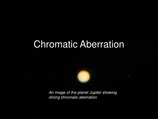
Chromatic Aberration, A closer look
110 likes | 305 Vues
Magnet. Ray used in maximum d c calculation. Danger zone. high. Energy Spread, o. Accelerator. low. +. Ion source. Divergence , o. Chromatic Aberration, A closer look. Are and correlated? Use MULE* to find out.

Chromatic Aberration, A closer look
E N D
Presentation Transcript
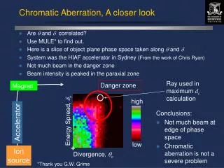
Magnet Ray used in maximum dc calculation Danger zone high Energy Spread, o Accelerator low + Ionsource Divergence, o Chromatic Aberration, A closer look • Are and correlated? • Use MULE* to find out. • Here is a slice of object plane phase space taken along and • System was the HIAF accelerator in Sydney (From the work of Chris Ryan) • Not much beam in the danger zone • Beam intensity is peaked in the paraxial zone Conclusions: • Not much beam at edge of phase space • Chromatic aberration is not a severe problem *Thank you G.W. Grime
Spherical Aberration, A closer look • Traditionally, spherical aberration is computed from the rectangular model (RM) • Rectangular model: B(z) = 0 z < 0 B(z) = B0 0 < z < L B(z) = 0 z > L • Results from this model agree with ray tracing codes that use B(r0, z) measured at r = r0 • Detailed studies have been done by Glenn Moloney • Measured field profiles B(r , z) at several r • Provides 3-D profile of True Fringe Field (TFF) • Numerical raytracing from measured B(r , z) reveals different spherical aberration coefficients! z L 0 Coefficient RM TFFM (x/ 2) -130 -130 (x/ 2) -390 +10 (y/ 3) -220 -190 (y/ 2) -390 +2
Spherical Aberration, A closer look • Coefficients calculated from the TFF model give aberration figures of different shapes compared to the rectangular model • The figure is more intense in the paraxial region - good!
200 mm 100 mm Set 5 nA 75 mm Uniform phase space Ion Source Brightness: Flux Peaking • Legge et al (1993) showed a 1 order of magnitude decrease in probe size required a 5 orders of magnitude increase in brightness for uniform model • True situation more complicated: 1 order of magnitude decrease in probe size requires 2 orders of magnitude increase in brightness For 5 nA divergence is 2.5 times less than uniform model so spherical aberration is reduced by a factor of 16 2 MeV He+ Current (pA)
grid shadow 525mm 130mm Stray DC Magnetic Fields: Parasitic aberration Without magnet With Magnet • Non-uniform stray DC fields are a problem • Shadows of a line focus on a fine grid should be straight line • Small bar magnet has severe effect • See large sextupole field component aberrations • Sources of stray DC fields in the MARC laboratory: • Iron gantry and stairway over the beam line • Steel equipment racks • Gas bottles • Stainless steel beam tube itself!
PIPE BEAM Deflect here grid beam shadow beam beam beam 130mm 525mm Stray DC Magnetic Fields: Aberrations of a beam pipe • Type 316 stainless steel beam pipe through quadrupole lenses • 10 mm internal diameter • Beam diameter 6 mm • Grid shadow pattern reveals aberrations • See strong effect from different deflections of the beam pipe! • Effect here produced by a few cm length • What effect does 8 m have?
Bstray(t) x x x x x x x x x x x x x x x x x x x x x x x x x x x x x x x x x x x x x x x imageshift x x x x x x x x x x x x x h Mh virtualobject Stray AC Magnetic Fields: Beam spot jitter • Stray AC field causes a shift in the virtual object position • The beam spot is scanned by the stray field in a complex fashion object lens http://www.meda.com/fm3page.htm
By (nT) Stray AC Magnetic Fields: Beam spot jitter • Stray AC fields cause virtual movement of the object collimator • Used a 2-D scanwith y-coilsdisconnected • Gives position asa function of timein map of Cu x-rays 3 mm
Stray AC Magnetic Fields Where: • M = Magnification = 1/Demagnification • q = beam particle charge • L = Length of beam line • E = beam energy • m = beam particle mass It is good to have: • High demagnification systems • Short systems On the Melbourne system it is required that: • Bstray < 20 nT for xi < 0.1 mm
Stray AC fields in MARC laboratory: Where from? • Field as a function of time tells the story • Start: 6pm April 18 2000 • Place: MP2 beam line, MARC laboratory To MARC lab 50 m