SPS Crab Cavity Support Structur e
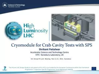
SPS Crab Cavity Support Structur e. Functional Specification. Why It’s Needed. Before installation into the LHC the cavities need to be tested within the SPS. To be tested in COLDEX area of SPS

SPS Crab Cavity Support Structur e
E N D
Presentation Transcript
SPS Crab Cavity Support Structure Functional Specification
Why It’s Needed • Before installation into the LHC the cavities need to be tested within the SPS. To be tested in COLDEX area of SPS • The cavities must be physically moved into the beam when testing is being conducted and then removed from the beam when the beam is being injected into the LHC. • This movement will be done when there is no beam currently in the SPS.
Load Requirements • Expected loads on the structure: • Cryomodule (including cavity) ~1555 kg (UK-4ROD) • Cryogenic service module ~500 kg • Circulators 2 x ~250 kg Total load ≈ 2505 kg • What’s not yet accounted for: • Weight of coaxials. • Stiffness of cryo transfer line [KB to give estimate]. • Stiffness of Y-chamber bellows. • Support table must provide a nominal movement of 2 x 510 mm per cycle. • Require lifetime for the testing is 1000 cycles.
Feasibility Study (30 minute movement) • Static support structure. • Mobile table mounted on static structure by linear bearings. • Cryomodule, circulators and cryo-service module mounted on the mobile table. • Transverse movement: • Two ball screws, either end of the cryomodule. • Each actuated by an electric (stepper)motor via gearing. • Torque for each screw: 0.8 Nm at 18.8 rad/s (constant speed). • Collimator motor pull-out torque 1.4 Nm at 18.8 rad/s.
Timescale • Max timescale allows for movement: 30 minutes. • Min possible timescale for movement: ~20 minutes (depending on motor). • Other considerations: • Max allowed acceleration on cryomodule is 0.2g • Minimise the forces on the outer wall of the power couplers. • Minimise the chance of the formation of particulates in the bellows. • Danger of damaging cryogenic transfer lines.
Positioning • Structure must be able to provide a six-degrees of freedom translation to the loads. • Four axes for vertical movement. • Two axes for transverse movement. • Transverse movement must be remote due to active alignment being used whilst under beam conditions. • Manual vertical adjustment.
Positioning Requirements • Positioning requirements:: • Max transverse movement range 550 mm • Max vertical movement range 50 mm • Positioning accuracy ±500 µm • Precision ±100 µm • Allowable transverse tilt 330 µrad
Additional Requirements • Use feedback from the beams closed-orbit for greater positioning accuracy. • BPMs either side of cryomodule. • Or, Using power output of the cavity. • Feedback for active adjustment due to closed orbit drift. • Ensure that the cavity's axis is within 1σ (0.7mm) of the beam.