Comprehensive Study of ATLAS RPC Trigger System for High Background Rates
360 likes | 468 Vues
Explore the design and performance of ATLAS RPC trigger system for handling high background rates at the LHC and SLHC. Understand RPC ageing effects and analysis for long-term performance. Investigate shielding techniques for background reduction.

Comprehensive Study of ATLAS RPC Trigger System for High Background Rates
E N D
Presentation Transcript
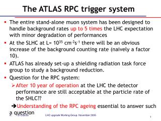
The ATLAS RPC trigger system The entire stand-alone muon system has been designed to handle background rates up to 5 times the LHC expectation with minor degradation of performances At the SLHC at L= 1035 cm-2s-1 there will be an obvious increase of the background counting rate (naively a factor 10). ATLAS has already set-up a shielding radiation task force group to study a background reduction. Question for the RPC system: After10 year of operation at the LHC the detector performance are still acceptable at the particle rate of the SHLC?? Understanding of the RPC ageing essential to answer such a question
Trigger chambers-3D view • ATLAS RPC system: • 1116 camere • 7000 m2 di rivelatore • 8500 strip panels • 350000 read-out channels Resistive Plate Chambers(RPC) (|η| < 1.05)
ATLAS barrel toroid 656 muon stations (of which 380 MDT/RPC) embedded inside the 8 coils
The RPC muon system ATLAS air-core toroid • Three RPC detector layers: • 2 in the middle station, 1 in the outer • Each layer: • 2 gas gaps and 4 readout planes for each detector element • Eta and Phi read-out copper strips panels, pitch ranging from 26.4 to 33.9 mm • Each gap: • 2 mm gas gap with bachelite electrodes • bakelite resistivity : ~ 1-4x1010 cm • Gas mixture: (C2H2F4) 94.7% - (C4H10) 5% - (SF6) 0.3% • Performance: • RPCs working in avalanche mode • Efficiency: > 98% • Time resolution: ~ 1-2 ns • Spatial resolution: 5-10 mm • Rate capability: ~ 1000 Hz/cm2
First level muon trigger in the barrel RPC LVL1 Muon trigger: • Six programmable thresholds • Low-pT trigger (RPC1+RPC2) 6 GeV/c • High-pT trigger (low-pT+RPC3) 10 Gev/c • Fast programmable geometrical coincidence (programmable cone opening) • Algorithm performed separately in eta and phi • Region of Interest: Dh x Df = 0.1 x 0.1 The RPC system provides: • LVL1 muon trigger • Bunch Crossing Identification • Second coordinate measurements
ATLAS shielding system Radiation shielding has been carefully studied and optimized to reduce background hall at a reasonable level
Muon background counting rate @L=1034 Background rate < 20 Hz/cm**2 in the barrel
Muon background counting rate @L=1035 • At L=1034 cm-2 s-1 the total counting rate (from Fluka/GCALOR MC) in the RPC system is ~10-20 Hz/cm2 • MC assumption have to be validate at the LHC start • Preliminary Montecarlo study at L=1035 cm-2 s-1 (M.Shupe et al) indicates that the background rate in the barrel muon system can be reduced at least of a factor 2 with: • a berillium beam pipe up to z=16m Additional shielding, modification of the forward layout are also investigated to further decrease the background rate • The expected rate in the Barrel muon system could beestimated~50-100 Hz/cm2
Beam pipe upgrade MC studies M.Shupe et al:ATL-Tech-2004-003
Background rate: preliminary studies It is possible to have the same rate in the barrel muon with a increase of 2 in luminosity changing to a Berillium pipe up to z=16m
The ATLAS RPC performance • Cosmic ray test performance • What we have learnt after the ageing tests at X5/ GIF on: • Modulo 0 • Production chamber tests
Cosmic ray tests:RPC performance Counting rate vs HV • BOS unit : dimension 1.1 x3.9 m2 • 4 gas volumes: 8 read-out strip panels Hz/cm2 Efficiency vs high voltage Cluster size Time distribution Nstrip=1.6 s = 2 ns
NIM A478 (2002) 271 First RPC Ageing test at GIF A 15 months ageing test performed on module-0at the GIF – X5 CERN irradiation facility. GIF-X5: Uniform irradiation with low energy gamma Source: 740 GBq 137Cs E g = 0.662 MeV RPC module-0 • Average expected counting rate in the ATLAS barrel ~100 Hz/cm2 ( including a safety factor ~ 5) • Total counts expected in 10 ATLAS years: 1010/cm2 • Total delivered charge: 0.3 C/cm2 ((100 Hz/cm2x 108x30pC/count)
First ageing test results Efficiency vs HV after Q = 0.36 C/cm2 (12 ATLAS years ) • The RPC module-0 after 12Y ageing shows a rate capability of ~300Hz/ cm2 • The ageing effect can be described in term of an increase of the operating voltage, due to an increase of the electrode total resistence (bakelite+graphite layer) • This test was complemented with more ageing tests in Roma2 (with 60Co source) for better understanding of the electrode ageing. -> a major deterioration of the graphite layer was observed. • The graphite layer was increased (keeping the same surface resistivity)
More ageing test at GIF 3 standard production chambers(BML-D) in the area. 6 gaps under ageing test. Beam 137Cs source (20 Ci); 660 keV photons
Plate resistivity study Each detector layer consist of two gas gaps with the gas flowing serially from the lower to the upper ones Only the 6 lower gaps were kept at the working point The upper ones are normally kept at HV=0 After ~2 years of operation, the plate resistivities of the upper chambers are consistent with the initial values The operating current is the primary cause of the observed increase in plate resistivity
Plate resistivity measurements The chambers are filled with Ar, and operated above 2kV, where the voltage drop across the gas remains constant. In these conditions, the I-V curve is linear and the ratio V/I gives the value of the resistance of the bakelite. Linear increase dominated by bakelite resistivity I-V characteristic in pure Ar
Ageing status at GIF Integrated charge : 240mC/cm2 corrisponding to:8 year ATLAS with a safety factor ~5
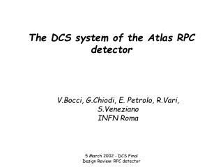
Understanding of ageing effects • Long time operation of RPCs is known to produce two main ageing effects: • Gradual increase of the total electrode resistivity (i.e. reduced rate capability) under high working currents. • Degradation of the inner surface of the plates due to operation with fluorine-rich gas mixtures, leading to an increase of the noise in the detector
How to reduce the increase of resistivity? • The on-going X5/GIF ageing test showed that it is possible to ‘moderate’ the ageing, precisely the increase of the bakelite resistivity it can be significantly reduced if the gas as well as the air in the environment humidity are kept at the level of40-50% RH
Plate resistivity evolution (1) r(20)= r(T)/exp(0.1(20-T)) OFF ext RH control ON
RPC efficiency after 7 ATLAS year Full source : rate ~500 Hz/cm**2 on station 1
Effect of F- production • The RPCs make large use of electronegative gases to control and limit the discharge process (C2H2F4and SF6 ) • The decomposition of such a gases under electrical discharge produces a significant concentration of fluoride radicals that can be detected in the RPC exhausted gas. • The F radicals may easily produce HF. Due to its high chemical reactivity, this represents a possible cause of the inner surface damaging if it is not quickly removed by the gas flow. • HF is an aggressive acid: it can harm the inner surface finding the eventual weak points of the oil protective coating.
Effect of F- production: noise increase • Electrode surface damages by HF produces • an increase of the noise rate and of the noise current. • It is enhanced by insufficient gas flow rate • a flow rate up to 1 Vol/h is required in Atlas • Recycled gas system mandatory with a purifier/filter to trap the impurities • A method for monitoring the Fluorine production in the gas has been developed in Roma2
F- Measurement setup TISAB + H2O • The TISAB (Total Ionic Strength Adjousting Buffer) neutralizes the effect of the electrode interfering substances such as OH- or metal traces. It keeps the PH around 5.5 • The F- can be measured by trapping the ions e.g. by bubbling the gas in water where the fluorine is detectable as Fluoride. Serial line SCALER: Singles doubles DAQ pH meter fluoride probe F˙ is measured by an Ion selective electrode probe(0.02 ppm F˙ sensitivity) , read by a PHmeter (used as impedance converter and prompt monitor) and recorded by DAQ Gas out (teflon) To exit bubbler Teflon container Magnetic stirrer RPC current Gas in Gas T,RH probe Gas system
More ageing test results • We have also seen that the i-Butane has a strong effect in reducing the Fluorine production • this suggests to maximize the i-Butane concentration in the RPC gas • we are however already close to the flammability limits of the mixture (with 5% i-buthane) • At SHLC could we change the mixture with more isobuthane? • Operation at low environment temperature, typically <24 C, is also essential to keep the noise at low level
Noise increases with Temperature 10200V chamber 4 gap 2 efficiency T=21C 9900V 9600V HVcorrected=9350V Working point T=31C 10250V 10500V 9900V From T= 21 C to T=31 C a factor 10 increase in the noise observed at the working point HVcorrected=9600V
Current increase with temperature Lecce group,Seoul 2004 • Both ohmic and multiplicative part of Igap increase with Temperature T=21C T=31C T=31C
A test of robustness after a major accident • A major malfunctioning of the recirculated gas system occurred at an integrated charge corresponding to ATLAS years • The chambers have continued operating at working point, under full irradiation, without any gas flow >>>the DCS system was not been able to shut down the HV • This lead to a damage to the internal surface of the plates, detectable from an increase of the working currents at closed source. • Moreover, the presence of pollutants on the surface caused an increase by a factor 4 of the ohmic currents of the gaps.
Working current increase (full source)
Increase isobuthane in the mixture • Increasing the isobutane concentration in the gas mixture to study a possible recovery of damaged bakelite RPCs. The isobutane component was raised from 5% to 15% • the performance of the chambers under this new gas mixture has also been studied.
Damage recovery – results (1) gap 1 gap 2 gap 3 gap 4 gap 5 gap 6 T Working currents Chambers were kept at 7kV We observed a decrease of the working currents on all the chambers The ohmic current showed also a steady and regular decrease. After the standard ATLAS mixture has been restored and ageing restarted I(mA) T (°C) gap 1 gap 2 gap 3 gap 4 gap 5 gap 6 T Ohmic currents T (°C) I(mA)
Damage recovery – results (2) Current evolution isotherms gap 1 gap 2 gap 3 gap 4 gap 5 gap 6 T gap 1 gap 2 gap 3 gap 4 gap 5 gap 6 T I(mA) I(mA) T (°C) T (°C) Ohmic currents Working currents
Conclusions (1) • All along the test (8 ATLAS year, safety factor 5), chamber performance (efficiency, cluster size, rate capability) have remained largely above the ATLAS requirements. • This ageing is equivalent to 16 SHLC year at a rate of 50Hz/cm**2 (with no safety factor) • From the RPC ageing studies we have learned : • Temperature , and RH of the enviroment and gas mixture must be kept at a proper value, • F- production could be reduced by isobuthane in the mixture
Conclusions (2) More R&D is necessary mainly on new gas mixture The first 1-2 year of ATLAS are necessary to draw more realistic conclusions on the behaviour of the RPCs at the SHLC For a correct background rate estimation at the SHLC it is important to test the Montecarlo calculation at the LHC start-up.