Download
1 / 2
20 likes | 101 Vues
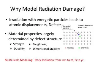
This paper discusses the radiation damage and activation issues in the Fermilab Booster magnets due to beam loss, focusing on epoxy resin insulation. It presents a simulation study on the integrated radiation dose to the epoxy and potential effects, addressing the demands of the neutrino program.

E N D
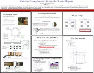
Radiation Damage Issues in the Fermilab Booster Magnets Eric Prebys,FNAL, Batavia, IL 60510 ABSTRACT The demands of the Fermilab neutrino program will require the lab’s 30+ year old 8 GeV Booster to deliver higher intensities than it ever has. Total proton throughput is limited by radiation damage and activation due to beam loss in the Booster tunnel. Of particular concern is the epoxy resin that acts as the insulation in the 96 combined function lattice magnets. This paper describes a simulation study to determine the integrated radiation dose to this epoxy and a discussion of the potential effects. Increasing Proton Demand • Total proton rate from Proton Source (Linac+Booster): • Booster batch size • Typical ~5E12 protons/batch • Booster repetition rate • 15 Hz instantaneous • Currently 7.5Hz average (limited by injection bump and RF cooling) • Beam loss • Damage and/or activation of Booster components • Above ground radiation • Total protons accelerated in Main Injector: • Maximum main injector load • Six “slots” for booster batches (3E13) • Up to ~11 with slip stacking (5.5E13) • RF stability limitations (currently ~4E13) • Cycle time: • 1.4s + loading time (1/15s per booster batch) The Fermilab Booster Magnet Design ANTIPROTON PRODUCTION • The Booster takes the 400 MeV Linac beam and accelerates it to 8 GeV. • From the Booster, beam can be directed to: • The Main Injector • MiniBooNE (switch occurs in the MI-8 transfer line). • The Radiation Damage Facility (RDF) • A dump. • The Booster is the only (almost) original accelerator in the Fermilab complex. • It maintains an average uptime of > 90% • 8E12 protons sent to the Main Injector every 2 seconds, to be accelerated to 120 GeV and delivered to the antiproton production trarget • ~1E16 protons per hour • Small compared to… NEUTRINO PROGRAM MiniBooNE-neutrinos from 8 GeV Booster proton beam (L/E~1): absolutely confirm or refute the LSND result: Running since fall 2002. To date has taken >5E20 protons:more protons than all other experiments in the 30 year history of the lab combined! 400 Mev Beam from Linac 8GeV Beam to Main Injector and MiniBooNE NuMI/Minos – neutrinos from 120 GeV Main Injector proton beam (L/E~100):precision measurement ofnm nt oscillations as seen in atmospheric neutrinos. Began running in March, 2005. Will ultimately use numbers of protons similar to MiniBooNE Yoke Water cooled coils Insulating epoxy resin. This is the major concern for radiation damage Nova – Same beam line as Minos, but detector built off axis. Would like 2-4 times the protons of Minos. • 472m in circumference • 24-fold periodic lattice • Each period contains 4 combined function magnets. • Magnets cycle in a 15 Hz offset resonant circuit. Old Main Ring Extraction Line Used for study cycles, RDF and “short batching” Limitations to Total Booster Flux Beam Loss Modeling LATTICE • Beam interaction: • Used MARS Monte Carlo • Simplified magnet model • Magnetic yoke • Coils • Insulating epoxy resin • Included magnetic field • Incident beam rate: • Based on observed beam loss • Some loss absorbed by collimation system, so used • 10% at 500 MeV • 1% at 5 GeV (~transition energy) • Convert this to incident beam rate • Recently average 5x10¹⁶ p/hr (1.4x10¹⁴) p/sec • Assume evenly divided over 96 magnets • 1.4x10¹⁰ p/sec @ 500 MeV • 1.4x10⁹ p/sec @ 5 GeV • “Long straights” high-b in vertical plane • “Short straights” high-b in horizontal plane Operational limit INJECTION Circulating Beam DC “Septum” Beam at injection 4 pulsed “ORBUMP” magnets 400 MeV H-beam from LINAC Stripping foil Upcoming Improvements and Projections • At injection, the 40 mA Linac H- beam is injected into the Booster over several “turns” (1 turn ~5E11). • The orbit is “bumped” out, so that both the injected beam and the circulating beam pass through a stripping foil. • Major Improvements: • New ORBUMP system (2005 shutdown) • Relocate L13 dump to MI-8 line (2005 shutdown) • New corrector system (2007) • 19th and 20th cavities added • Performance • Rep rate (after 2005) • 7.5 Hz -> 8-9 Hz • Total protons (by end 2008) • 8E16 pph -> 1.45E17 pph • Batch size (by end 2008): • 5E12 -> 5.5E12 EXTRACTION sec Typical acceleration cycle DC “doglegs” work with ramped 3-bump (BEXBUMP) to maintain 40p aperture below septum Fast (~40 ns) kickers
Longitudinal Profiles Residual Radiation Inspection of Magnets Radiation Damage • These figures show the longitudinal energy deposition (Gy/sec) at 500 MeV (top) and 5 GeV (bottom) • Based on this distribution, we choose the first 50 cm as the shower max, which is used to find the maximum energy deposition in the lateral cross sectional profile • This shows the residual activation (mSv/hr) after 30 days of running and 1 day cool down due to 500 MeV (top) and 5 GeV (bottom) incident beam. • It is consistent with surveyed activation in the Booster, which gives us confidence in the model. Discussion Peak Energy Deposition • Unfortunately, there is little information on the details of the epoxy used in the Booster magnets. • In typical epoxy resins of this type, detectable radiation damage begins to occur with exposure at the few hundred kGy level, but the first symptoms are embrittlement and an increase in moisture absorption. • The former should not be a worry unless it becomes extreme. • The latter might be a concern in that moisture could affect the conductivity of the resin; however, as the coils are in vacuum, this is not an issue. • Epoxy resins in the magnets at the Tristan ring at KEK had exposure as high as 10 MGy and while they were visibly darkened they continued to function properly. Integrated Dose • The simulated energy deposition results in roughly 1-2x10-17 Gy per accelerated proton. • The Booster has delivered roughly 1.1021 protons over its 30+ year life • This corresponds to 10-20 kGy. • However, keeping in mind that the Booster was much less efficient in the past and the nonuniformity of beam loss, its reasonable to assume that some areas of the Booster have gotten as much as 100-200 kGy. • The Booster is projected to deliver 5-10x1021 • This will necessarily involved reducing losses, but it still reasonable to assume that some areas of the epoxy will receive as much as 1 MGy or so. Conclusions • Our studies indicate that the epoxy resin used as an insulator in the magnets of the Fermilab Booster may have received integrated radiation doses as high as 100 kGy over the life of the machine. • The increased proton flux needed by the neutrino program could mean that some areas will receive as much as 1 MGy over the next ten years. • While these numbers are within the range where epoxy resins have been shown to work in the past, they are definitely at a level which causes some concern, particularly given our lack of details about the exact epoxy used. • It is therefore extremely important to keep beam loss at a minimum in the coming years and to try to keep it as uniform as possible to avoid excessive localized dosage. • Further study is warranted, and should a magnet fail for other reasons, it will be important to inspect the condition of the epoxy. • These figures show the transverse energy deposition (Gy/sec) in the first 50 cm at 500 MeV (top) and 5 GeV (bottom) • This shows that the epoxy sees as much as 10-3 Gy/sec at each energy