Download

1 / 1
10 likes | 153 Vues
DEVELOPMENT of Cogging at the fermilab booster. K. Seiya # , S . Chaurize , C. Drennan , W. Pellico , A . K. Triplett, A. Waller, Fermilab , Batavia, IL 60510, USA. Abstract

E N D
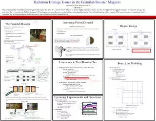
DEVELOPMENT of Cogging at the fermilab booster K. Seiya#, S. Chaurize, C. Drennan, W. Pellico, A. K. Triplett, A. Waller, Fermilab, Batavia, IL 60510, USA Abstract The development of magnetic cogging is part of the Fermilab Booster upgrade within the Proton Improvement Plan (PIP). The Booster is going to send 2.25E17 protons/hour which is almost double the present flux, 1.4E17 protons/hour to the Main Injector (MI) and Recycler (RR). The extraction kicker gap has to synchronize to the MI and RR injection bucket in order to avoid a beam loss at the rising edge of the extraction and injection kickers. Magnetic cogging is able to control the revolution frequency and the position of the gap using the magnetic field from dipole correctors while radial position feedback keeps the beam at the central orbit. The new cogging is expected to reduce beam loss due to the orbit changes and reduce beam energy loss when the gap is created. The progress of the magnetic cogging system development is going to be discussed in this paper. Field error BOOster operation Calculated integration of the difference of rfcounts. Measured integration of the difference of rfcounts. The Booster is a resonant circuit synchrotron with an operating frequency of 15Hz, which is synchronized to the 60Hz power line. Variations in the power line frequency and voltage result in deviation of the Booster cycle’s length and starting point for acceleration. The magnetic field error changes the revolution frequency through the cycle which results in a change in position of the extraction kicker gap. Field error with feedback Intensity with 11 batch injection in the MI. One rf count results in 0.2A through the correctors with the constant gain in both simulations and measurements. The MI has a harmonic number of 588 and beam from the Booster every 66.67 ms. The batch from the Booster has to be injected to the specific MI bucket location. Magnetic cogging Measurements with constant gain. Measurements with gain curve. The magnetic cogging controls the revolution frequency by changing the magnetic fields. The rf count difference (Dcount) between current cycle and the reference cycle is determined approximately every 10 msec and this difference is integrated through the entire Booster cycle. A gain, G, is applied to the integrated count difference and the resulting signal is sent to the corrector power supplies. The total dipole field in the Booster is then the sum of the fields due to the dipole correctors and the main gradient magnets. Simulation with constant gain. Gain curve. Simulation with gain curve. Synchronization to the MI • Even with the total rf counts in a cycle regulated to match the reference cycle, the time delay between OAA and Bdot is changing from cycle to cycle. The total number of bucket counts on a reference cycle is also changing from MI/RR cycle to cycle. Three delays determine the trigger time of the Notcher for a synchronous transfer to the MI or RR. • 1. The delay between Bdot and OAA. • 2. The delay between Bdot and OAA on the reference cycle. • 3. The constant signal delay between the digital output of the cogging controller and the input to the Notcher firing system. The bucket slippage in 1 msec with 1 A on 48 correctors. Block diagram of the cogging control loop. Beam in the MI with cogging. Cogging SYSTEM The mountain range plots shows that the 2nd to 4th batch were injected from the Booster to the MI every 66.6 msec. The resistive wall monitor was measured for 5.6 msec on each trace and for 0.22 sec in vertical direction. The upper plot shows that the kicker gaps lined up with an edge of the batch with cogging. The lower shows the kicker gap in the middle of the batch without cogging. Cogging system layout. • Bdot: beginning of acceleration • BRF: Booster RF signal • MIRF: MI RF signal • OAA: MI revolution marker • 1.Start counting BRF at Bdot. • 2. Count the BRF cycles that occur within every MI • revolution period (approx. 10 msec). • 3. Compare the count with the one from the reference • cycle and take their difference. • 4. Integrate the difference. • 5. Multiply the integral by a gain from a gain table. • 6. Send the product via the DAC output to the • correctors. Beam in the MI without cogging. CONCLUSION Magnetic cogging was able to control the position of the extraction gap using the dipole correctors. The magnetic cogging allows the extraction kicker gap to be created anytime in a cycle and reduces beam energy loss at the kicker location. Final bucket position was within +/- 1 target bucket with feedback as expected. When beam is sent to MI, the extraction kicker gap was synchronized to the desired MI bucket. Cogging system layout. DAC outputs The VXI controller module has 4 each, 14 bit DAC outputs. Figure shows output signals from 3 of the DAC’s; integrated count difference, the gain curve and the product of the integrated count difference times the gain, respectively from top to bottom. The integrated count difference multiplied by the gain curve is the cogging feedback signal. VXI controller module DAC outputs