Safety Interlocks
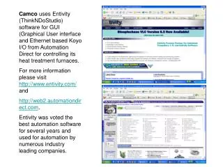
Camco uses Entivity (ThinkNDoStudio) software for GUI (Graphical User interface and Ethernet based Koyo I/O from Automation Direct for controlling its heat treatment furnaces. For more information please visit http://www.entivity.com/ and http://web2.automationdirect.com .

Safety Interlocks
E N D
Presentation Transcript
Camco uses Entivity (ThinkNDoStudio) software for GUI (Graphical User interface and Ethernet based Koyo I/O from Automation Direct for controlling its heat treatment furnaces. For more information please visit http://www.entivity.com/ and http://web2.automationdirect.com. Entivity was voted the best automation software for several years and used for automation by numerous industry leading companies.
Connectivity Center allows efficiently configure, manage and operate all digital and analog input/outputs of the entire system. Safety hardware interlocks are implemented on electromechnical relays separately from the I/O system. Software just duplicates hardware actions and send alarm or warning text message to the GUI screen.
Main Screen allow operator to monitor interlocks, alarm, warning and recipe related text messages. All temperature, vacuum, gas delivery information is available here. Operator can start, stop programs and navigate to other screens.
Process Screen allows operator to view recipe execution and all temperature, vacuum, gas delivery information is available here. Operator can start, stop programs and navigate to other screens.
Recipe Screen allow operator to enter or edit all recipe parameters, All data parameters are retentitive (stored to a hard drive).
Manager Screen allow operator to manage screen access passwords, configure data log files and navigate to other screens.
Graph screens allow to view temperature and vacuum data in chart form. Operator can change scales scroll time in real time.
Safety Interlocks • The schematic shows safety hardware interlocks. Every safety related parameter is monitored via electromechanical fail safe sensor. Failed safe electromechanical relays K7, K8, K9, K10, K11, K12, K13, K14 and K 15 are connected to the following devices: • Water flow switch • N2 pressure switch • Over temperature switch • Transformer temperature switch • H2 pressure switch • Panel switch • Argon pressure switch • H2 burner current detection switch • Bell clamp switch • Bell down switch • Air pressure switch.
The schematic shows safety hardware interlocks output circuit. Heater Contactor K2, can be energized only if only all the safety relays are on. All these relay are DPDT relays. One of the NO contacts are connected in series to allow system software to turn the contactor on. In case is any of these relay is off main contactor will turn off and stop heating. Second NO contact of these relay is connected to the system digital input module to notify software and operator on the computer screen which of the interlocks is open. At the same time system software duplicates hardware and turn off the correspondent digital output which controls the heater contactor.
The schematic shows safety hardware interlocks output circuit. H2 process valve is interlocked via NO contact of the relay K14. Relay K14 will be turn off if any the safety condition to open H2 valve is not satisfied. • In case of power failure H2 normally closed solenoid valve will close, stop H2 flow. Nitrogen normally open valve will open and N2 gas will purge the H2 out. • In addition to these hardware interlocks system software duplicates all this functions and provides the following additional level of protection: • If during any of the program segments H2 gas was used, software will keep the burner on during the entire program. • At the end of such program software will ensure an additional 30 minutes ( valid range from 30-60 min) nitrogen purge to ensure that all H2 gas is displaced from the chamber prior to allow raise the bell.