Download
1 / 26
390 likes | 685 Vues
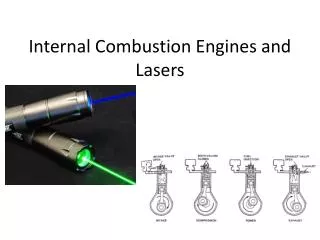
Thermodynamic Analysis of Internal Combustion Engines. P M V SUBBARAO Professor Mechanical Engineering Department IIT Delhi. Work on A Blue Print Before You Ride on an Actual Engine…. It is a Sign of Civilized Engineering…. FUEL. A I R. Ignition. Fuel/Air Mixture.

E N D
Thermodynamic Analysis of Internal Combustion Engines P M V SUBBARAO Professor Mechanical Engineering Department IIT Delhi Work on A Blue Print Before You Ride on an Actual Engine…. It is a Sign of Civilized Engineering….
FUEL A I R Ignition Fuel/Air Mixture Combustion Products Actual Cycle Intake Stroke Compression Stroke Power Stroke Exhaust Stroke SI Engine Cycle
Actual SI Engine cycle Total Time Available: 10 msec Ignition
Fuel injected at TC A I R Air Combustion Products Actual Cycle Intake Stroke Compression Stroke Power Stroke Exhaust Stroke Early CI Engine Cycle
A I R Modern CI Engine Cycle Fuel injected at 15o bTC Air Combustion Products Actual Cycle Intake Stroke Compression Stroke Power Stroke Exhaust Stroke
Thermodynamic Cycles for CI engines • In early CI engines the fuel was injected when the piston reached TC • and thus combustion lasted well into the expansion stroke. • In modern engines the fuel is injected before TC (about 15o) Fuel injection starts Fuel injection starts Early CI engine Modern CI engine • The combustion process in the early CI engines is best approximated by • a constant pressure heat addition process Diesel Cycle • The combustion process in the modern CI engines is best approximated • by a combination of constant volume and constant pressure Dual Cycle
Thermodynamic Modeling • The thermal operation of an IC engine is a transient cyclic process. • Even at constant load and speed, the value of thermodynamic parameters at any location vary with time. • Each event may get repeated again and again. • So, an IC engine operation is a transient process which gets completed in a known or required Cycle time. • Higher the speed of the engine, lower will be the Cycle time. • Modeling of IC engine process can be carried out in many ways. • Multidimensional, Transient Flow and heat transfer Model. • Thermodynamic Transient Model USUF. • Fuel-air Thermodynamic Mode. • Air standard Thermodynamic Model.
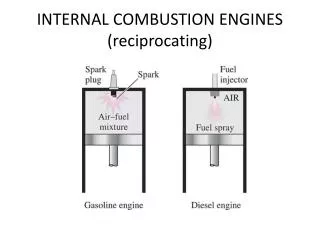
Ideal Thermodynamic Cycles • Air-standard analysis is used to perform elementary analyses of IC engine cycles. • Simplifications to the real cycle include: • 1) Fixed amount of air (ideal gas) for working fluid • 2) Combustion process not considered • 3) Intake and exhaust processes not considered • 4) Engine friction and heat losses not considered • 5) Specific heats independent of temperature • The two types of reciprocating engine cycles analyzed are: • 1) Spark ignition – Otto cycle • 2) Compression ignition – Diesel cycle
Otto Cycle FUEL A I R Ignition Qin Qout Air Otto Cycle TC Fuel/Air Mixture Combustion Products BC Actual Cycle Compression Process Const volume heat addition Process Expansion Process Const volume heat rejection Process Intake Stroke Compression Stroke Power Stroke Exhaust Stroke
Air-Standard Otto cycle Process 1 2 Isentropic compression Process 2 3 Constant volume heat addition Process 3 4 Isentropic expansion Process 4 1 Constant volume heat rejection Compression ratio: Qin Qout TC v1 BC v2 TC BC
First Law Analysis of Otto Cycle 12 Isentropic Compression AIR 23 Constant Volume Heat Addition Qin AIR TC
3 4 Isentropic Expansion AIR 4 1 Constant Volume Heat Removal Qout AIR BC
First Law Analysis Parameters Net cycle work: Cycle thermal efficiency: Indicated mean effective pressure is:
Effect of Compression Ratio on Thermal Efficiency Typical SI engines 9 < r < 11 k = 1.4 • Spark ignition engine compression ratio limited by T3 (autoignition) • and P3 (material strength), both ~rk • For r = 8 the efficiency is 56% which is twice the actual indicated value
Effect of Specific Heat Ratio on Thermal Efficiency Specific heat ratio (k) Cylinder temperatures vary between 20K and 2000K so 1.2 < k < 1.4 k = 1.3 most representative
Factors Affecting Work per Cycle The net cycle work of an engine can be increased by either: i) Increasing the r (1’2) ii) Increase Qin (23”) 3’’ P (ii) 3 4’’ Qin 4 Wcycle 4’ 2 (i) 1 1’ V2 V1
k = 1.3 Effect of Compression Ratio on Thermal Efficiency and MEP
Qin Qout Air BC Compression Process Const pressure heat addition Process Expansion Process Const volume heat rejection Process Ideal Diesel Cycle
Air-Standard Diesel cycle Process 1 2 Isentropic compression Process 2 3 Constant pressure heat addition Process 3 4 Isentropic expansion Process 4 1 Constant volume heat rejection Cut-off ratio: Qin Qout TC BC v2 TC v1 BC
Thermal Efficiency For cold air-standard the above reduces to: recall, Note the term in the square bracket is always larger than one so for the same compression ratio, r, the Diesel cycle has a lower thermal efficiency than the Otto cycle Note: CI needs higher r compared to SI to ignite fuel
Thermal Efficiency Typical CI Engines 15 < r < 20 When rc (= v3/v2)1 the Diesel cycle efficiency approaches the efficiency of the Otto cycle Higher efficiency is obtained by adding less heat per cycle, Qin, run engine at higher speed to get the same power.
Qin Qin Qout Air Dual Cycle TC BC Const volume heat addition Process Compression Process Const pressure heat addition Process Expansion Process Const volume heat rejection Process Thermodynamic Dual Cycle
Dual Cycle Process 1 2 Isentropic compression Process 2 2.5 Constant volume heat addition Process 2.5 3 Constant pressure heat addition Process 3 4 Isentropic expansion Process 4 1 Constant volume heat rejection Qin 3 2.5 3 Qin 2 2.5 4 2 4 1 Qout 1
Thermal Efficiency Note, the Otto cycle (rc=1) and the Diesel cycle (a=1) are special cases:
The use of the Dual cycle requires information about either: • the fractions of constant volume and constant pressure heat addition • (common assumption is to equally split the heat addition), or • ii) maximum pressure P3. • Transformation of rc and a into more natural variables yields For the same inlet conditions P1, V1 and the same compression ratio: For the same inlet conditions P1, V1 and the same peak pressure P3 (actual design limitation in engines):
For the same inlet conditions P1, V1 and the same compression ratio P2/P1: For the same inlet conditions P1, V1 and the same peak pressure P3: Pmax “x” →“2.5” Pressure, P Pressure, P Po Po Specific Volume Specific Volume Tmax Otto Dual Diesel Diesel Dual Temperature, T Temperature, T Otto Entropy Entropy