Download
1 / 34
340 likes | 593 Vues
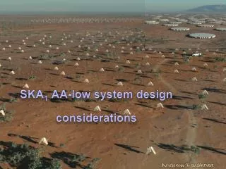
SKA AA-low: LPD antenna (SKALA) & path towards AAVS0 at Cambridge. Eloy de Lera Acedo University of Cambridge. Overview. Introduction Current status of SKALA (LPD antenna) Low Noise Amplifier for SKALA SKALA tests and AAVS0 (16-element array) Important numbers Summary and conclusions.

E N D
SKA AA-low: LPD antenna (SKALA) & path towards AAVS0 at Cambridge Eloy de LeraAcedo University of Cambridge AAVP 2011: Taking the AA programme into SKA Pre-Construction 12-16 December, 2011 - ASTRON, Dwingeloo
Overview • Introduction • Current status of SKALA (LPD antenna) • Low Noise Amplifier for SKALA • SKALA tests and AAVS0 (16-element array) • Important numbers • Summary and conclusions
Evolution: from BLU to SKALA Impedance Dual polarisation Sky coverage Cost BLU Impedance Dual polarisation Sky coverage Cost Impedance Dual polarisation Sky coverage Cost w-SKALA Toothed log periodic Impedance Dual polarisation Sky coverage Cost SKALA
SKALA: SKALog-periodic Antenna 1.6 m 1.3 m * GND mesh is 1.5 x 1.5 m.
Mass production of SKALA and LNA • Some numbers: • Cost of antennas for AAVS1 is around 150€/element. • Cost of antenna for AAVS2 is targeted at 75€/element (this is for the 2 polarisations and includes the electronics). • Weight of each arm would be 1.56 kg if made of steel wire.
Low Noise Amplifier for SKALA • Frequency range 70 to 450MHz • Gain > 20dB • Gain flatness, as flat as possible consistent with meeting other spec. parameters • Noise temperature < 30K at 450MHz • P1dB, high enough to allow astronomical observations to be made at Lords Bridge • Power consumption < 100mW • Unconditionally stable at both input and output ports • Differential source (antenna), single-ended load • High Level of Common Mode Signal Rejection
Schematic AVAGO MGA-16516
LNA+antenna simulated performance (includes a 20dB gain second stage on chip)
LNA+antenna simulated performance (includes a 20dB gain second stage on chip)
Simulated A/T for SKA1(with log-periodic antenna) - A/T shown is A/T of 1 antenna x N (number of antennas in a 180 m station with elements spaced 1.5 m apart) x 50 stations. • η (radiation efficiency) = 90% • D (directivity) • Tsky (sky noise temperature) following Tsky = 1.691*(freq[GHz].^-2.751) + 4.875 K • Tamb (ambient temperature) = 295 K • Trec (receiver noise temperature) -> Assuming ideal amplifier with: • Zopt (optimum noise impedance) = 100 Ω • Rn (noise resistor) = 10 Ω • Fmin (minimum noise figure) = 0.3 dB -> 21 K
Effect of Soil/GND – (Soil B – 5% humidity) Even a bigger pitch may be possible!
SKALA tests and AAVS0 • 16 dual-polarised SKALA elements. • Aim: • Test realistic SKA AA-low front-end technology in an array environment: • Effect of cables. • Effect of ground mesh/soil. • Effect of mutual coupling on noise and pattern. • Challenges: • Measure the pattern in an array environment. Options: • Use of known field source: NF, FF. • Use data from interferometry experiment. • Cost: • Estimated total cost is 5-10 K€ depending on tools and equipment needed for the tests. ADC: 1GS/s 50 - 100m all optical Data e/o Control e/o Analogue Sync. e/o
Lord’s Bridge Observatory SKALA-AAVS0
Upcoming tests: • December 2011: • Impedance test with “dummy” board. • January 2011: • Single element pattern measurement in outdoor test range, Perth? • Single element pattern measurement in outdoor test range, UK. • Noise matching with integrated LNA in reverberation chamber, UK. • Impedance tests on AAVS0. • February-March 2011: (with Roach back-end) • Noise tests on AAVS0: pointing the array to hot and cold patches of the sky. • Pattern tests on AAVS0: (compare with analytical/EM models - UCL) • Interferometry experiment: full correlation/correlation with high gain antenna • Known source: Near field source (no back-end needed), minicopter? • More tests... Any suggestion? Plug into other back-ends?
Important numbers • Noise: • <30 K @ 450 MHz. • Sky coverage – A/T: • Meets DRM specifications down to +/- 45o at all frequencies. • Frequency band: • Potential to go down to 50 MHz (lower arm). • Foot-print: 1x1 m possible (lower arm). • Cost: • Targeted to 75 € including LNA and ground mesh.
Single-Dual band • Low-band: high gain element, OK. • High-band: low gain element? Not so easy... Getting down to 30 K with a low gain antenna in a 3:1 band is not that easy. You will probably need a high gain element anyway and rather large.
Summary and conclusions • Antenna+LNA pair meets DRM requirements. • In early 2012 noise and pattern tests for AAVS0. • Mass production prototypes are in their way (75€/element).
Thank you! Any questions? SKALA2 (ICRAR) SKALA3 (Cambridge) SKALA1 (Cambridge) SKALA4 (ASTRON) SKALA0 miniSKALA (Cambridge)