Download
1 / 19
190 likes | 294 Vues
Design of the OOI Global Nodes John Trowbridge (Woods Hole Oceanographic Institution) 17 December 2013. Agenda: Hi-level description of Ocean Observatories Initiative Hi-level description of Global platforms, spatial & temporal coverage, control, flow of power & comms

E N D
Design of the OOI Global NodesJohn Trowbridge (Woods Hole Oceanographic Institution)17 December 2013 • Agenda: • Hi-level description of Ocean Observatories Initiative • Hi-level description of Global platforms, spatial & temporal coverage, control, flow of power & comms • Lankhorst to follow with details siting, sensors, sampling
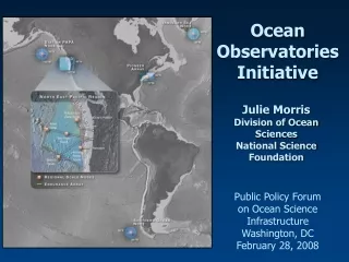
Ocean Observatories Initiative (OOI) Components: Regional Scale Nodes Coastal & Global Scale Nodes Endurance Array Cyberinfrastructure Education & Public Engagement Schedule: Initiated Sep 2009 5.5 years Construction 25 years Operations Organization: NSF = Sponsor Ocean Leadership = Prime Implementing Organizations = Subs
Baseline Global Array Schematic Glider Flanking Mooring Flanking Mooring Glider Glider Profiler Mooring SurfaceMooring
Surface Mooring • Surface Buoy • Controller/logger: sampling and telemetry • Power controller: generation, storage and distribution • Power from solar/wind with rechargeable batteries • Fleet BroadBandsatellite communications • Meteorology, air & water PCO2, waves • Near-Surface Instrument Frame (15 m) • Secondary controller • Power from Surface Buoy • EM chain communications with Surface Buoy • Pumped CTD, fluorometer, point velocity • Riser • Internal battery power on sensors • Inductive communications of sensors with Surface Buoy • pH at two depths and CTD at multiple depths • Upward-looking ADCP at 500 m
Profiler Mooring • Surface Piercing Profiler (top 150 m, 2 one-way per day) • Secondary controller, Internal battery power; Irridium satellite communications • Fluorometer, PCO2, DO, CTD, absorption, nitrate, irradiance • Proposed Plan B under review to replace Surface Piercing Profiler: Gliders + additional sensors on Surface Mooring • Subsurface Sphere (292 m) • Secondary controller • Internal battery power; inductive communications with Controller Cage • Upward-looking bio-acoustic sonar • Wire-Following Profiler (303 to 2616 m, 1 one-way per day) • Internal battery power; inductive communications with Controller Cage • Fluorometer, dissolved oxygen, CTD, velocity • Controller Cage (2620 m) • Controller • Internal battery power • Inductive communications with GSPP, Subsurface Sphere, Wire-Following Profiler • Acoustic communications with gliders
Flanking Mooring • Subsurface Sphere (30 m) • Secondary controller • Internal battery power • Inductive communications with Controller Cage • Fluorometer, pH, dissolved oxygen • Riser • Internal battery power on sensors • Inductive comms sensors with Controller Cage • Fixed CTD at multiple depths, ADCP at 500 m • Controller Cage (1507 m) • Controller • Internal battery power • Inductive comms with Riser sensors and Subsurface Sphere • Acoustic communications with gliders
Gliders • Sample to 1000 m on fixed paths around triangular mooring array • Acoustic communications with Flanking Moorings and Hybrid Profiling Mooring • Irridium satellite communications • Fluorometer, dissolved oxygen, CTD
Baseline Global Array Schematic Glider Flanking Mooring Flanking Mooring Glider Glider Profiler Mooring SurfaceMooring
Sensors on Gliders • 2-wavelength fluorometer • Dissolved oxygen • CTD
Global Surface Piercing Profiler (GSPP) Plan B • GSPP to be removed from Hybrid Profiler Mooring. • 2 Gliders to perform as virtual mooring: • Carrying most sensors required for GSPP. • Test at Papa confirmed station-keeping, schedule-keeping, and vertical resolution meet L2 Science Requirements • Additional fixed sensors to be added to the buoy, the NSIF, and at 40, 80 and 130 m. • Critical Design Review Feb 2014.
Conclusions of Glider as Virtual Mooring at Papa • Virtual mooring capability exists • Station-, schedule-keeping, and vertical resolution meet L2 Science Requirements • Site dependencies • Baseline energy estimate • Final sensor mix and power loads TBD • Require multiple platforms per site
GSM Preliminary Conceptual Redesign Note: This conceptual design is preliminary, and will be detailed before the Critical Design Review (CDR) in February, 2014.
Additional Facts • GSM Power: • Given environmental conditions, expect average 100-150 W of power from wind and solar (variable over the course of the year). • Based on Pioneer I, expected SUMO power consumption ~ 80 W. • GSM Communications: Primary communications via Fleet BroadBand (INMARSAT). Rate ~ 100kbits/s. To send all data, ~160 MB per month (dependent on sampling strategy). • GSM Buoy Dimensions: Diameter ~ 10 ft, weight ~ 8500 lbs. • GWFP Power: 360 Ah batteries enable 1 one-way profile per day (800 km cumulative profiling distance). • Comms between WFPs and SIO Controller: 120 Bytes/s via inductive communication. • Comms between SIO Controller and Glider: 12-60 Bytes per second, depending on acoustic signal quality.