OorIQ endian mode design guide.
130 likes | 379 Vues
OorIQ endian mode design guide. Background. Because Customers always confuse between PowerPC Local bus and NOR Flash connection, External Flash Programmer vs PowerPC local bus and Debugging tool vs PowerPC local bus.

OorIQ endian mode design guide.
E N D
Presentation Transcript
Background • Because Customers always confuse between PowerPC Local bus and NOR Flash connection, External Flash Programmer vs PowerPC local bus and Debugging tool vs PowerPC local bus. • Introduce Endian mode, PQ Local bus with NOR Flash connection, data bytes translation behavior. • Hope to help customers to know how to design NOR Flash with PQ Local bus.
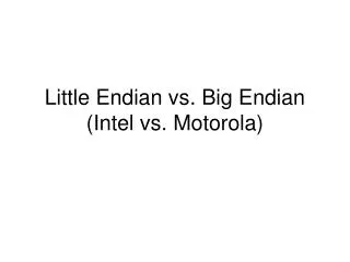
Endian mode View Endianness and Memory Data Entered into Both mode Offset Data Size 0x00 0x00facade 32-bit word 0x07 0x1357 16-bit short 0x0b ‘p’,’o’,’w’,’e’,’r’ five 8-bit byte Big Endian View of Data in Memory 0x00 Byte 00 01 02 03 04 05 06 07 08 09 0a 0b 0c 0d 0e 0f Little Endian View of Data in Memory 0x00 Byte 00 01 02 03 04 05 06 07 08 09 0a 0b 0c 0d 0e 0f
PowerPC connect to 16bit flash component as 8bit PowerPC Local bus 16 bit Flash Note : PowerPC LAD0 – Flash D7 . . PowerPC LAD7 – Flash D0 PowerPC LAD31 . . . . LAD15 . . . LAD8 LAD7 . . LAD0 Flash D0 . D7 D8 . . . D15 D0 - LSB D15 - MSB LAD31 - LSB LAD0 - MSB
PowerPC connect to 16bit flash component as 16bit PowerPC Local bus 16 bit Flash Note : Hardware connection PowerPC LAD0 – Flash D15 . . PowerPC LAD7 – Flash D8 PowerPC LAD8 – Flash D7 . . PowerPC LAD15 – Flash D0 PowerPC Flash LAD31 . . . . LAD15 . . . LAD8 LAD7 . . LAD0 D0 . D7 D8 . . . D15 Freescale reference board design
0x12 0x34 Reading first 8bit by CodeWarrior debugging tool Example: The first 8 bits on Flash Is 0x1234(D0~D8) 2 bytes PowerPC Flash CPU read MByte1 D0 . D7 FByte0 D7 . D0 0x12 0x34 Save bin image Byte0Byte1…… Byte0Byte1 0x12 0x34 0x12 0x34 FByte1 MByte0 Byte0 0x34 Byte1 0x12 0x12 0x34 Writing Bin to Flash by Programmer Byte 0 0x12 0x12 0x12 FByte0 D0 . D7 Byte 1 0x34 0x34 FByte1 0x34 External Flash Programmer
0x12 0x12 0x34 0x34 Reading first 16bit by CodeWarrior debugging tool Example: The first 16 bits on Flash Is 0x1234(D0~D16) PowerPC Flash D0 . D7 D8 . D15 D15 . D8 D7 . D0 MByte1 FByte0 Save bin image Byte0Byte1…… Byte0Byte1 0x34 0x12 0x34 0x12 FByte1 MByte0 Byte0 0x34 Byte1 0x12 0x34 0x12 Writing Bin to Flash by External Programmer as little endian mode D0 . D7 D8 . D15 Byte 0 0x34 0x34 FByte0 0x34 FByte1 Byte 1 0x12 0x12 0x12 External Flash Programmer
Reading Flash Manufacturer ID by CodeWarrior debugging tool command line
Reading Flash Manufacturer ID by CodeWarrior debugging tool command line
Reading Flash Manufacturer ID by CodeWarrior debugging tool command line Example : P2041RDB : 16 bit Flash – - Please pay attention on Address shift by PowerPC >change m:0xfff00aaa 0x00aa 16bit >change m:0xfff00554 0x0055 16bit >change m:0xfff00aaa 0x0090 16bit >display m:0xfff00000 16bit fff00000 $0001 .. >change m:0xfff00aaa 0x00f0 16bit
Workshop • A:Please use CodeWarrior command line to read Flash ID. • B: PCIe Link status check _Write value into PCX1_config_address as 0x84000004, _Check the value of on PCX1_config_data, If get 0x16000000. The PCIe link is done. • C: PCIe endpoint device ID 1. Write value into PCX1_config_address as 0x80000018 2. write 0x0001_0300 to into PCX1_config_data 3. Write value into PCX1_config_address as 0x80010000, 4. Check the value of on PCX1_config_data, you will get PCIe device ID.
Below procedure is the uart1 ini script by CodeWarrior Command Line, We assume the Uart line rate is 115200, So you should modify UDLB and UDMB value based on CCB 400MHz. """""""""""""""""""""""""""""""""""""""""""""""""""""""""""""""""""""""""""""""""""""""""""""""""""""""""""""""""""""""""""""""""""""""""" 13.4.2 Baud-Rate Generator LogicEach UART contains an independent programmable baud-rate generator, that is capable of taking the CCBclock input and dividing the input by any divisor from 1 to 216 – 1.The baud rate is defined as the number of bits per second that can be sent over the UART bus. The formulafor calculating baud rate is as follows:Baud rate = (1/16) × (CCB clock frequency/divisor value)Therefore, the output frequency of the baud-rate generator is 16 times the baud rate.The divisor value is determined by the following two 8-bit registers to form a 16-bit binary number:• UART divisor most significant byte register (UDMB)• UART divisor least significant byte register (UDLB) """""""""""""""""""""""""""""""""""""""""""""""""""""""""""""""""""""""""""""""""""""""""""""""""""""""""""""""""""""""""""""""""""""""""" 115200 = (1/16) x ( 396 x 1000 x 1000/divisor value ). divisor value ~= 215 = 0xD7 change 0xe0004503 0x83 8bit // Uart1 ULCR change 0xe0004500 0xD7 8bit // Uart1 UDLBchange 0xe0004501 0x00 8bit // Uart1 UDMBchange 0xe0004503 0x03 8bit // Uart1 ULCRchange 0xe0004502 0x07 8bit // Uart1 UFCR