Thermocouples
Thermocouples. Most frequently used method to measure temperatures with an electrical output signal. What are thermocouples?.

Thermocouples
E N D
Presentation Transcript
Thermocouples Most frequently used method to measure temperatures with an electrical output signal.
What are thermocouples? • Thermocouples operate under the principle that a circuit made by connecting two dissimilar metals produces a measurable voltage (emf-electromotive force) when a temperature gradient is imposed between one end and the other. • They are inexpensive, small, rugged and accurate when used with an understanding of their peculiarities.
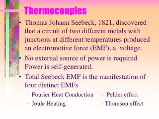
Thermocouples Principle of Operation • In, 1821 T. J. Seebeck observed the existence of an electromotive force (EMF) at the junction formed between two dissimilar metals (Seebeck effect). • Seebeck effect is actually the combined result of two other phenomena, Thomson and Peltier effects. • Thomson observed the existence of an EMF due to the contact of two dissimilar metals at the junction temperature. • Peltier discovered that temperature gradients along conductors in a circuit generate an EMF. • The Thomson effect is normally much smaller than the Peltier effect.
How thermocouples work • It is generally reasonable to assume that the emf is generated in the wires, not in the junction. The signal is generated when dT/dx is not zero. • When the materials are homogeneous, e, the thermoelectric power, is a function of temperature only. • Two wires begin and end at the same two temperatures. Generally, a second order Eqn. is used.
Material EMF versus Temperature With reference to the characteristics of pure Platinum Chromel Iron emf Copper Platinum-Rhodium Alumel Constantan Temperature
Thermocouple Effect • Any time a pair of dissimilar wires is joined to make a circuit and a thermal gradient is imposed, an emf voltage will be generated. • Twisted, soldered or welded junctions are acceptable. Welding is most common. • Keep weld bead or solder bead diameter within 10-15% of wire diameter • Welding is generally quicker than soldering but both are equally acceptable • Voltage or EMF produced depends on: • Types of materials used • Temperature difference between the measuring junction and the reference junction
Thermocouple Tables (EMF-Temperature) • Thermocouple tables correlate temperature to emf voltage. • Need to keep in mind that the thermocouple tables provide a voltage value with respect to a reference temperature. Usually the reference temperature is 0°C. If your reference junction is not at 0°C, a correction must be applied using the law of intermediate temperatures.
Reference Temperature Systems and Zone Boxes • Ice Baths • Accurate and inexpensive • Electronically Controlled References • Require periodic calibration and are generally not as stable as ice baths, but are more convenient.
Zone boxes • A zone of uniform temperature that insures all connections made within the zone are at the same temperature.
What thermocouple materials should be used? • Depends on requirements: • Temperature range? • Required accuracy • Chemical resistance issues • Abrasion or vibration resistance • Installation requirements (size of wire) • Thermal conduction requirements
Thermocouple Material Vs EMF Types T, J, and K are most commonly used thermocouples (see Table 16.8 of the “Handbook”).
Simple TC Model “EMF-Temperature Sketch” 1 • Two materials • Material A (+) • Material B (-) • Plus and minus refers to how the emf changes with temperature. Number junctions around circuit and draw 2 3 3 B Measured Emf 2 emf A 1 T meter T junction Temperature
Law of Intermediate Metals 2) Insertion of an intermediate metal into a thermocouple circuit will not affect the emf voltage output so long as the two junctions are at the same temperature and the material is homogeneous. • Permits soldered and welded joints.
A Demonstration of the Law of Intermediate Metals 6 1 2 4 5 3 6 4 Fe (+) C (-) P (+) C Measured Emf 5 emf 3 2 Fe 1 Signs of the materials used T ref T 2 and 4 T measured Tcandle Temperature
Law of Intermediate Temperatures If a thermocouple circuit develops a net emf1-2 for measuring junction temperatures T1 and T2, and a net emf2-3 for temperatures T2 and T3, then it will develop a net voltage of emf1-3 = emf1-2 + emf2-3 when the junctions are at temperatures T1 and T3. emf1-2+emf2-3= emf1-3 T2 T1 T3 T2 T1 T3
A Demonstration of the Law of Intermediate Temperatures emf1-2+emf2-3= emf1-3 C emf23 emf13 emf emf12 Fe T 1 T 2 T 3
A Demonstration of the Law of Intermediate Temperatures 4 5 3 1 2 Hot Zone 4 C 2 3 Measured Emf emf Fe 1 T ref T hot T measured
If a thermocouple circuit of materials A and C generates a net emfA-C when exposed to temperatures T1 and T2, and a thermocouple of materials C and B generates a net emfC-B for the same two temperatures T1 and T2, then a thermocouple made from materials A and B will develop a net voltage of emfA-B = emfA-C + emfC-B between temperatures T1 and T2. • Sometimes useful in the calibration of different thermocouple wires.
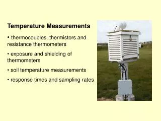
Temperature Measurement Errors • Conduction • Convection • Radiation • Response Time • Noise • Grounding issues and shorts, especially on metal surfaces