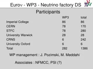
Project Participants
Lessons Learned and Flight Results from the F-15 Intelligent Flight Control System Project John Bosworth Project Chief Engineer February 2006 NASA, Dryden Flight Research Center. Nasa Dryden Flight Research Center Responsible test organization for the flight experiment

Project Participants
E N D
Presentation Transcript
Lessons Learned and Flight Results from the F-15 Intelligent Flight Control System ProjectJohn BosworthProject Chief EngineerFebruary 2006NASA, Dryden Flight Research Center
Nasa Dryden Flight Research Center Responsible test organization for the flight experiment Flight, range and ground safety Mission success Nasa Ames Research Center Development of the concepts Boeing STL Phantom Works Primary flight control system software (Conventional mode) Research flight control system software (Enhanced mode) Institute for Scientific Research Neural Network adaptive software Academia West Virginia University Georgia Tech Texas A&M Project Participants
Demonstrate Revolutionary Control Approaches that can Efficiently Optimize Aircraft Performance in both Normal and Failure Conditions Advance Neural Network-Based Flight Control Technology for New Aerospace Systems Designs F-15 IFCS Project Goals
Motivation These are survivable accidents IFCS has potential to reduce the amount of skill and luck required for survival 4
Implemented on NASA F-15 #837 (SMTD and ACTIVE projects) Use Existing Reversionary Research System Limited Flight Envelope Failures Simulated by Frozen Surface Command (Stab) or Gain Modification on the Angle of Attack to Canard Feedback IFCS Approach
NASA F-15 #837 Aircraft Description Production design P/Y thrust vectoring nozzles F100-PW-229 IPE engines with IDEECs Canards Quad digital flight control computers with research processors and quad digital electronic throttles • No mechanical or analog backup • Digital fly-by-wire actuators • Four hydraulic systems Electronic air inlet controllers ARTS II computer for high computation research control laws
Flight Envelope For Gen 2 Mach < 0.95
Adaptation algorithm implemented in separate processor Class B software Autocoded directly from Simulink block diagram Many configurable settings Learning rates Weight limits Thresholds, etc. Control laws programmed in Class A, quad-redundant system Protection provided by floating limiter on adaptation signals Limited Authority System Single Channel 400 Mhz Adaptive Algorithm Safety Limits Research Controller 4 Channel 68040 Conventional Controller
NN Floating Limiter Upper range limit (down mode) Max persistence ctr, downmode Rate limit drift, start persistence counter Floating limiter Window size Sigma pi cmd (pqr) Lower range limit (down mode) Tunable metrics Window delta Drift rate Persistence limiter Range limits Black – sigma pi cmd Green – floating limiter boundary Orange – limited command (fl_drift_flag) Red – down mode condition (fl_dmode_flag
Assess handling qualities of Gen II controller without adaptation Activate adaptation and assess changes in handling qualities Introduce simulated failures Control surface locked (“B matrix failure”) Angle of attack to canard feedback gain change (“A matrix failure”) Re-assess handling qualities with simulated failures and adaptation. Report on “Real World” experience with a neural network based flight control system Flight Experiment
Ability to suppress initial transient due to failure Trade-off between high learning rate and stability of system Ability to re-establish model following performance Ability to suppress cross coupling between axes No existing criteria Adaptation Goals
Grey Region: Based on model-to-be-followed Maximum noticeable dynamics (LOES) Handling Qualities Performance Metric
Funded Gen 1 Indirect adaptive system Identify changes to “plant” Adapt controls based on changes LQR model based controller (online Ricatti solver) Gen 2 Direct adaptive Feedback error drives adaptation changes Dynamic inversion based controller with explicit model following Future Potential Gen 2+ Different Neural Network approaches Single hidden layer, radial basis, etc Gen 3 adaptive mixer and adaptive critic Project Phases
Generation 1 Indirect Adaptive System
ARTS II Indirect Adaptive Control Architecture Sensors Pretrained Neural Network PTNN Derivatives DCS Neural Network PID Derivative Estimation Derivative Bias Control Commands Derivative Estimates DCS Derivatives + + Derivative Errors Closed Loop Learning Open Loop Learning + Pilot Inputs SCE-3 SCSI
System flown in 2003 – Open loop only Gain calculation sensitive to identified derivatives Uncertainty in estimated derivative too high Difficult to estimate derivatives from pilot excitation Normally correlated surfaces Better estimation available with forced excitation Many derivatives required for full plant estimation However more are required when LatDir couples with Long No immediate adaptation with failure Requires period of time before new plant can be identified Indirect adaptive might be more suited for clearance of new vehicles rather than failure adaptation Indirect AdaptiveExperience and Lessons Learned
Generation 2 Direct Adaptive System
Gen II Direct Adaptive Control Architecture(Adaptive) pilot inputs Research Controller Feedback Error Control Allocation Model Following - + Direct Adaptive Neural Network Sensors
Gen 2 Currently in flight test phase Simplified Sigma-Pi neural network No higher order terms Limits on Weights Current Status Qdot_c = Q_err*Kpq*[1 – W1 – W2] + Q_err_int*Kiq*[1 - W1 – W3] + Q_err_dot*Kqd*[1 – W1]
Effect of Canard Multiplier Apparent Plant Sym. Stab Canard AoA A/C Plant Can. Mult. Control System
-0.5 canard multiplier at flight condition 1; with & without neural networks
Initial simulation model had high bandwidth Majority of system performance achieved by the dynamic inversion controller Direct adaptive NN played minor role Dynamic Inversion gains reduced to meet ASE attenuation requirements Much harder to achieve desired performance NN contribution increased Initial performance objective emphasized transient reduction and achieving model following after failure Piloted simulation results showed that reducing cross coupling was more important objective Explicit cross terms in NN required for failure cases Relying on disturbance rejection alone doesn’t work (also finding of Gen 1) Direct AdaptiveExperience and Lessons Learned
Liapunov proof of bounded stability Necessary but not sufficient proof of stability Many cases of limit cycle behavior observed Other analytic methods required for ensuring global stability Dynamic Inversion controller contributes significantly to cross coupled response in presence of surface failure (locked) Redesigned yaw loop using classical techniques NN’s require careful selection of inputs Presence of transient errors “normal” for abrupt inputs in non- adaptive systems Existence of transient errors tend to drive NN’s to “high gain” trying to achieve impossible Significant amount of “tuning” required for to achieve robust full envelope performance Contradicts claim of robustness to unforeseen failures Piloted nonlinear simulation required Direct AdaptiveExperience and Lessons Learned
Adaptive controls status Currently collecting “real world” flight experience Interactions with structure biggest challenge Fruitful area for future research F-15 IFCS project is providing valuable research to promote adaptive control technology to a higher readiness level Conclusions