Download
1 / 34
350 likes | 643 Vues
Ultrasound Microscopy and High Frequency Coded Signals. Antti Meriläinen, Edward Hæggström. Ultrasound Microscopy What it is?. Using high frequency acoustic waves for mm-/µm-scale imaging Method is non-destructive It “Sees” inside the sample

E N D
Ultrasound Microscopy and High Frequency Coded Signals Antti Meriläinen, Edward Hæggström
Ultrasound MicroscopyWhat it is? • Using high frequency acoustic waves for mm-/µm-scale imaging • Method is non-destructive • It “Sees” inside the sample • Ultrasound images differences of acoustic impedances
Ultrasound Imaging Amplitudeimage TOF image
Ultrasound MicroscopyBasic techniques Single transducer pulse-echo Phase Arrays http://en.wikipedia.org/wiki/Ultrasonic_testing http://www.nde.com/phased_array_technology.htm
Focused Ultrasound Transducer [Yu, Scanning acoustic microscopy and its applications to material characterization, 1995]
Tx/Rx for USM • TX • Pulser, delta spike excitation • Gated sinus wave • For high frequencies ~1 GHz • RX • Protection circuit & Pre-amplifier • (Envelope detector / pulse shaper) • Oscilloscope Camacho, J., Fritsch, C.: ‘Protectioncircuits for ultrasoundapplications’ Ultrasonics, Ferroelectrics and FrequencyControl, IEEE Transactions, 2008, 55, (5), pp.1160-1164
Challenges with current techniques • Delta spike excitation • Stress for transducer and sample • Energy/amplitude variation with high PRF • Gated sinus • Stress for transducer and sample • Uncertainty of Time-of-Fly (TOF) • Depth resolution
Coded USM • Coded signals • Electronics • Signal generation • Switch and timing • Preamplifier • Signal Synthesis • Ultrasound measurements • RF-design • Components • PCB layout
Coded Signals • Tx signal is wave packed • Frequency can be programmed • Phase can be programmed • Envelope (amplitude over time) can be programmed • Example linear frequency modulation (LFM)/chirp
Cross Correlation dt descript depth resolution dt depends on bandwidth dt
Coded Signal and SNR SNR =1 SNR =10
Signal generationNumerical vector to Electric signal • Arbitrary waveform generators • Digital to Analog converter (DAC) • Bandwidth up to 120 MHz (2 GS/s) • If you have money: 5.6 GHz (24 GS/s) • High frequency signal generators • Output: continuous sine wave • Frequency range up to 4+ GHz • Narrow modulation bandwidth (less than 1 kHz)
Modulation techniques • Modulation = change carrier wave by signal • Amplitude modulation (AM) • Quadrature amplitude modulation (QAM) • Frequency modulation (FM) • Phase Modulation (PM) • Many other …. Modulation
QAM / IQ-modulation • AM: • QAM:
TRF370417 Modulator • Arbitrary/modulation bandwidth is 2*120 MHz • dt = 4.2ns • Center output frequency is set by Local oscillator • Output Bandwidth is NOT maximum output frequency
Modulator outputs Q Lo I 1 cm RF Out
Preamplifier Design Modulator -> Attenuator(-60 dB) -> Preamplifier(+55 dB) • Amplification • Cascade design • Voltage range • Max/Min signal input strenght • Impedance maching • Input impedance • Output impedance • DC-blocks • Capacitors and inductos for high frequencies • Same component can be tunet for different band
Switch and Timing • Receiving during transmission is impossible • Transducer delay line gives time limit for coded signal • Typically 0.3 – 5 µs • Signal generator limits coded length 8 µs • Maximize signal time and minimize switching time
Switch designing • Power handling • Bandwidth • Attenuation • Insertion loss (Smaller is better) • Isolation (Higher is better) • Switching time • Glitch • AC/DC coupling • Control voltages
Timing • Circuit based on AVR µController • Programmable • Predictable • Timing resolution is 62.5 ns • AVR trigs AWG and oscilloscope and controls the switches
Coded USM • Coded signals • Electronics • Signal generation • Switch and timing • Preamplifier • Signal Synthesis • Ultrasound measurements • RF-design • Components • PCB layout
Signal generationHow to generate I and Q • I and Q are numerical signals that can be generated by Matlab LO cos LO sin RF LO cos LO sin Q I AWG X X X X + LP LP I & Q RF Q I Modulator Matlab
Results with 100 – 300 MHz Transmitted signal Received A-line B-scan image
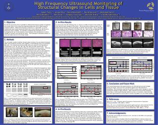
Results from 2010: 30 – 70 MHz Coded signal • Signal-to-noise ratios (SNR) of surface echoes were estimated to compare coded excitation and delta spike excitation • Preliminary results showed that coded chirp signal excitation increased mean SNR (16±3) dB for 75 MHz transducer Pulse-echo measurement using a coded 5 Vpp chirp signal excitation at 30-70 MHz (left) and a 33 Vpp delta spike excitation (right). The coded excitation increased mean SNR (16±3) dB.
Higher frequency and coded signals • Higher frequency gives resolution • Modulator shift arbitrary band (Not increase bandwidth) • Coded signals may improve SNR/CNR • Cross correlation is sensitive for noise which has same band than signal • Bad modulator can generated ”noise” (Feedthrough) • Effective bandwidth can be tuned by arbitrary code • Transducer bandwidth • Attenuation in immersion liquid • Arbitrary codes able multitone transmission
RF design • Impedance matching • Single-end vs. Differential signals • Available IC components: • Amplifiers • Attenuators • Switches • Modulators / Demodulators • Power detector • Clock generator (PLL/VCO) All components are SMD
Single-End vs. Differential signals • Differential signals: • Single supply • No ground loops • Longer signal path • Reduces common-mode noise (noise from ground) • Paired signal is required • Single • Simpler design • (Dual supply) There is amplifiers for conversion
Available IC components Amplifiers • Low noise (Pre. Amp.) • Noise figure <1dB • Gain ~20dB • Gain blocks • 50 Ω line driver • Power amplifier (Linear amplifier) • Differential amplifier • Variable gain amplifier (VGA)