Beam-Based Calibration
Beam-Based Calibration. Screen calibration. Two screens with BPM in between. Scan beam position with upstream dipole/corrector. Absolute calibration. One screen and dipole/corrector. Can only calibrate changes in BPM position, not absolute position.

Beam-Based Calibration
E N D
Presentation Transcript
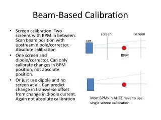
Beam-Based Calibration • Screen calibration. Two screens with BPM in between. Scan beam position with upstream dipole/corrector. Absolute calibration. • One screen and dipole/corrector. Can only calibrate changes in BPM position, not absolute position. • Or just use dipole and no screen at all. Can predict change in transverse offset from change in dipole current. Again not absolute calibration screen screen cor BPM Most BPMs in ALICE have to use single screen calibration
ALICE BPMs ARC2 AR2-BPM-1 AR2-BPM-2 AR2-BPM-3 AR2-BPM-4 AR2-BPM-5 AR2-BPM-6 ST4 ST4-BPM-1 ST4-BPM-2 ST1 ST1-BPM-1* ST1-BPM-2 ARC1 AR1-BPM-1 AR1-BPM-2 AR1-BPM-3 AR1-BPM-4 AR1-BPM-5 AR1-BPM-6 ST2 INJ-BPM-1 INJ-BPM-2 INJ-BPM-3 INJ-BPM-4 INJ-BPM-5 ST3 ST3-BPM-1 ST3-BPM-2 Data only collected for a few BPMs Only INJ-BPM-3 used two screens (absolute calibration) all the others are relative calibrations INJECTOR INJ-BPM-1 INJ-BPM-2 INJ-BPM-3 INJ-BPM-4 INJ-BPM-5 *Need to investigate ST1-BPM1 again, only raw NWSE readings were taken, not BPM position
INJ-BPM-3 INJ-HVCOR-02 used INJ-3 INJ-2 Beam position done by Gaussian fit (ImageJ)
ST2-BPM-01 Vary AR1-DIP-03 Measure beam position on ST2-OTR1 This assumes beam starts on axis at dipole entrance and trace OTR positions back to this origin to predict position on ST2-BPM-01. Can also not use screen at all and just predict the transverse displacement at the BPM caused by the change in dipole current The measured BPM zero-position is actually -7.3 mm. But this could just be due to incorrect assumptions. The two methods give 0.49 and 0.45 for the slope. i.e. BPM overestimates the real beam position by factor of ~2.
Conclusions True BPM position = B*(Measured BPM position) + A *should check this data again see slide 2 Only horizontal position looked at (what about INJ-BPM-03 vertical, gives different result to horizontal) Can we say confidently that the BPM zero-positions are correct, and it’s just the scaling that’s wrong ?
ST1-BPM-1 Beam position OTR-1 Vary ST4-DIP-03 Measure beam position on ST1-OTR1 DIP-03 current The point of this plot is just to show the nice linearity between beam position on screen and dipole current. This linearity in beam transverse displacement is predicted by the simple analytic equations you use for the dipole-screen calibration. Nice to confirm this. But the shift #1509 that collected this data did not record the BPM readings in mm, they just recorded the NWSE voltages.