Download

1 / 11
170 likes | 374 Vues
EPOCH 1000 Series Procedure Conventional Angle Beam Calibration. Basic Setup :. TRANSDUCER + WEDGE A541S-SM ABSA-5T-45 TEST BLOCK TB7541-1 (IIW). CABLE BCM-74-6 COUPLANT D-12. 4 Steps for an Angle Beam Calibration 1. Locate the Beam Index Point (BIP) of the Probe.

E N D
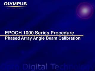
EPOCH 1000 Series ProcedureConventional Angle Beam Calibration
Basic Setup: • TRANSDUCER + WEDGE • A541S-SM • ABSA-5T-45 • TEST BLOCK • TB7541-1 (IIW) • CABLE • BCM-74-6 • COUPLANT • D-12
4 Steps for an Angle Beam Calibration • 1. Locate the Beam Index Point (BIP) of the Probe. • 2. Verify the Refracted Angle • 3. Calibrate for Distance (Using the Auto-Cal Feature) • 4. Calibrate for Sensitivity
Adjust parameter settings for angle beam calibration. • Follow through the menu list to change parameters in best possible order • Under • Velocity – Set Shear Wave Velocity for 1018 Carbon Steel, 0.1280 in/µs • Range – Set to 10 inches for best visibility • Under • Pulser – Set to Square Pulser • Frequency – Set to 5 MHz • Energy – Set to100 V • Damp – Set to 50 Ohms • PRF – Set to Auto Mode
Adjust parameter settings for angle beam calibration Cont. • Under • Filter – Set the filter to 2.0-21.5 • Under • Angle – set to 45° • Increase until response signal from transducer is visible
Locating the Beam Index Point: • Identifies the point on wedge where the maximum energy is being transferred out • Instructions: • Align wedge on top of IIW block near zero mark with probe pointing towards the IIW’s curved edge. • Peak up signal* from the 4 inch reflector. • Peak memory function may be use to aid in peaking up the signal • When signal is maxed, the zero mark on IIW block will correspond to the BIP point on the wedge. • Mark position on wedge that lines up with the zero mark on the IIW block. Locating beam index point set up Locating the beam index point Gage and A-Scan setup
Verifying the Refracted Angle: • Refracted angle of the wedge may vary due to properties of test materials or wear and tear of transducer wedge. • Instructions: • Set wedge on bottom of IIW block with probe pointing towards large circular hole. • Peak up* the received signal. • Peak memory function may be use to aid in peaking up the signal • Using indication of BIP, reference the angle on IIW Block. • Under the menu select the parameter to enter the correct value. • Adjust the angle value with the knob. Verifying refracted angle setup Verifying refracted angle Gage and A-Scan setup
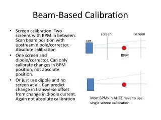
1” 4” • Calibrating for Distance • Adjusts the Zero and Velocity parameters to obtain accurate digital measurements during inspections • Instructions: • Line up the probe beam index point (BIP) above the zero mark. • Position Gate 1 around the 4” reflector. • Use the Auto-XX% feature to bring the 4” reflection to desired reference screen height • For best results the probe should not be moved at all from this point until calibration is finished. Set up for distance calibration A-Scan showing both 9” and 4” echoes
Calibrating for Distance Cont. • Under the menu, select to Calibrate the Zero. • Enter 4.000 for the value of the zero calibration by adjusting the knob. • Press the Check key to select and to finish the zero calibration. Calibrating for Zero Value using 4” echo
Calibrating for Distance Cont. • Without moving the probe, position gate over the 9” reflection echo. • Use the Auto XX% feature to bring the 9” reflection to the desired screen height • Under the menu, select to Calibrate the velocity. • Enter 9.000 for the value of the velocity calibration by adjusting the knob. • Finish Calibration by selecting by pressing the Check button. Calibration for Velocity Value using 9” echo
0.600” side drilled hole • Calibrating for Sensitivity • Sets up reference gain to size flaws • Instructions: • Set Probe to face the large circular hole and aim the BIP towards the 0.600” deep side drill hole • Peak up the echo from the side drill hole. • Position gate over the signal above the 1 grid. • Use the Auto XX% function to adjust the side drill hole reflection to the reference height. • Use 2ndF+GAIN (REF dB) to set the reference gain level. • Use the knob to add or subtract scanning gain for sizing flaws during inspection by adjusting the gain value. Set up for sensitivity calibration Locking the reference gain to add/subtract scanning gain