Conventional Facilities & Beam Stability
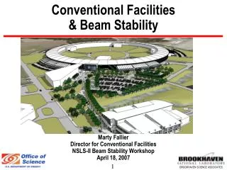
Conventional Facilities & Beam Stability. Marty Fallier Director for Conventional Facilities NSLS-II Beam Stability Workshop April 18, 2007. Stability Dependent on Conventional Facilities. Stability goals driven by conventional facility design Stability of storage ring tunnel floor

Conventional Facilities & Beam Stability
E N D
Presentation Transcript
Conventional Facilities & Beam Stability Marty Fallier Director for Conventional Facilities NSLS-II Beam Stability Workshop April 18, 2007
Stability Dependent on Conventional Facilities • Stability goals driven by conventional facility design • Stability of storage ring tunnel floor • Vibration < 25 nm PSD from 4-50hz • Stability of experimental floor • Vibration level of < 25 nm PSD from 4-50hz for general floor area • Vibration level for 1 nm resolution beam lines requires further definition but appears achievable with proper correlation • Thermal stability of storage ring tunnel environment • +/- 0.1o C for 1 hour time constant • Thermal stability of experimental floor • +/- 0.5o C for 1 hour time constant
NSLS II Facility Overview NSLS JPSI LOB (1 of 5) NSLS II CFN BLOC Service Bldgs (1 of 5) Access Tunnel
NSLS II Facility Overview cont’d • NSLS II Floor Plan • BLOC – Booster/LINAC/ Operations Center • LOB – Lab Office Buildings (3 base scope up to 5 future) • Service Buildings (5) • RF Area • Tunnel Area • Electrical Mezzanine • Experimental Floor • Access Corridor 2 3 2 1 3 4 2 3 3 3 2 2
NSLS II Facility Overview cont’d Lab-Office Bldg 8 Access Corridor Experimental Floor 7 6 SR Tunnel Electrical Mezzanine (above tunnel) 5 Service Bldg 1st Floor (earlier concept)
CF Program for Vibration Management • Assessment of “green-field” conditions • Studies by Colin-Gordon Associates & N. Simos • On-going monitoring program • Identification and mitigation of cultural sources (where feasible) • FE Modeling of site and facility design • Needed to understand & predict facility response • Design optimization tool • Analysis of other facilities (CFN, APS & SPring 8 thus far) • Draw upon lessons learned • Provide input for model • Model performance verification • During & after construction, implement monitoring and maintenance program
Specific Vibration Mitigation Strategies • “Monolithic” slab for accelerator and experimental floor • Slab thicknesses based on vibration modeling results • Possible use of polymer admixtures and concrete layering for enhanced damping characteristics (access corridor & service bldgs) • Isolation of bldg structure, access corridor and mechanical spaces from tunnel and experimental floor slab • Inertia bases and isolation of piping, ducts and machinery from tunnel and experimental floor slabs • Low flow velocity design for ducts and piping • Specification and commissioning of equipment and systems to include precision alignment, balancing & vibration measurement • Orientation of service bldgs to maximize distance of machinery sources from tunnel and experimental floor slabs
Ring Building Section Bldg structure Isolated from tunnel and experimental Floor Isolation Joint or Void Space Electrical Mezzanine Isolated Grade Beam Tunnel Roof Ratchet or Shield Wall Isolation Joint Earth Shield Berm Access Corridor Experimental Floor “Monolithic Joint” Isolated Pier for Column Tunnel Floor
Tunnel Design - Ring Building Section Need to assure that vibration mitigation measures are carried out at Ring building interfaces with other structures and where systems enter building or tunnel Non-vibrating Equipment Rotating Machinery Non-vibrating Equipment Rotating Machinery Distance determined by modeling & empirical analysis Section at Lab Office Building and Service Building
Vibration Studies • Studies of NSLS II “green field” conditions indicate an existing cultural vibration level of ~20 nm • Does not factor in reduction due to expected filtering effect of slab • Does not factor in cultural vibration reductions that can be achieved • Does not factor in addition from self-inflicted sources • Additional modeling and analysis is on-going to predict the value of these factors to arrive at an expected value for NSLS II • N. Simos will present in-depth discussion of modeling analysis and initial results in breakout session
Service Bldg Results • Concern about location of rotating machinery in service buildings near tunnel when positioned on infield side of Ring Bldg • Initial results show contribution from service bldg is minor (0.4nm) if source is properly isolated and located ~30 ft from tunnel • Additional mitigation can be applied to reduce energy transfer to ground beneath service building and reduce contribution even further • Conclusion – service building, and associated economy for utility routing, in infield appears workable 30 ft
Temperature Stability • Key temperature stability requirement is tunnel air @ +/- 0.1C (+ /-.18 F) at any given location over 1 hour • Key parameter is temperature stability and repeatability vs. absolute accuracy. • This level of stability has been achieved at other facilities and BNL has achieved even better stability in microscopy lab applications • The relatively steady state heat load and the high thermal mass of the tunnel make this quite achievable • Thermal modeling will be performed to confirm concepts and optimize system design
CF Beam Stability Path Forward • Continue vibration study and modeling to provide added assurance that design will yield desired performance • Assess impacts of proposed NSLS II design choices and equipment on vibration environment • Optimize vibration resistant design vs the quantity of concrete & steel in the tunnel and experimental floor slabs to contain costs • Identify local sources of vibration from on-site/off-site operating facilities to enable remediation (i.e. repair roads, balance machinery etc.) and optimize operating environment for NSLS II • Continue collaboration with other facilities to understand vibration performance and verify model accuracy • Perform thermal modeling to confirm stability goals can be achieved