Binary Image Processing Techniques and Morphological Operations
This lecture delves into binary image processing and connected components extraction, focusing on morphological filtering methods for feature extraction. It discusses the critical process of thresholding to separate objects from the background and explores the challenges of classifying regions as single or multiple classes. Methods for cleaning up thresholding results, including removing noise and tiny objects, are highlighted. The operational principles of dilation and erosion are examined, showcasing their application in edge detection and improving object uniformity. Practical examples, including blood cell detection, illustrate the concepts.

Binary Image Processing Techniques and Morphological Operations
E N D
Presentation Transcript
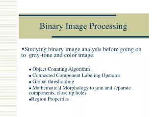
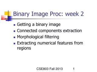
CSE803 Fall 2013 Binary Image Proc: week 2 Getting a binary image Connected components extraction Morphological filtering Extracting numerical features from regions
CSE803 Fall 2013 Quick look at thresholding Separate objects from background. 2 class or many class problem? How to do it? Discuss methods later.
Cherry image shows 3 regions • Background is black • Healthy cherry is bright • Bruise is medium dark • Histogram shows two cherry regions (black background has been removed) Use this gray value to separate CSE803 Fall 2013
CSE803 Fall 2013 Choosing a threshold Common to find the deepest valley between two modes of bimodal histogram Or, can level-slice using the intensities values a and b that bracket the mode of the desired objects Can fit two or more Gaussian curves to the histogram Can do optimization on above (Ohta et al)
CSE803 Fall 2013 Connected components Assume thresholding obtained binary image Aggregate pixels of each object 2 different program controls Different uses of data structures Related to paint/search algs Compute features from each object region
Example red blood cell image • Many blood cells are separate objects • Many touch – bad! • Salt and pepper noise from thresholding • How useable is this data? CSE803 Fall 2013
Cleaning up thresholding results • Can delete object pixels on boundary to better separate parts. • Can fill small holes • Can delete tiny objects • (last 2 are “salt-and-pepper” noise) CSE803 Fall 2013
Removing salt-and-pepper • Change pixels all (some?) of whose neighbors are different (coercion!): see hole filled at right • Delete objects that are tiny relative to targets: see some islands removed at right CSE803 Fall 2013
CSE803 Fall 2013 Simple morphological cleanup Can be done just after thresholding -- remove salt and pepper Can be done after connected components are extracted -- discard regions that are too small or too large to be the target
Dilation & Erosion • Basic operations • Are dual to each other: • Erosion shrinks foreground, enlarges Background • Dilation enlarges foreground, shrinks background Slides contributed by Volker Krüger & Rune Andersen, University of Aalborg, Esbjerg http://www.google.com/url?sa=t&rct=j&q=&esrc=s&source=web&cd=1&cad=rja&ved=0CC8QFjAA&url=http%3A%2F%2Fweb.cecs.pdx.edu%2F~mperkows%2FCLASS_479%2Flectures_2012_479%2F2011.%25200001.%2520A._Introduction_to_Morphological_Operators.ppt&ei=_fMtUpvQNYbwyAGN0IAo&usg=AFQjCNGJat2gHPKxO_WlYkw3gzv6XxEJIQ&sig2=5McelJco9akafAA7xC1B6Q
A first Example: Erosion • Erosion is an important morphological operation • Applied Structuring Element:
1 1 1 Example for Erosion Input image Structuring Element Output Image
1 1 1 Example for Erosion Input image Structuring Element Output Image
1 1 1 Example for Erosion Input image Structuring Element Output Image
1 1 1 Example for Erosion Input image Structuring Element Output Image
1 1 1 Example for Erosion Input image Structuring Element Output Image
1 1 1 Example for Erosion Input image Structuring Element Output Image
1 1 1 Example for Erosion Input image Structuring Element Output Image
1 1 1 Example for Erosion Input image Structuring Element Output Image
Another example of erosion • White = 0, black = 1, dual property, image as a result of erosion gets darker
Counting Coins • Counting coins is difficult because they touch each other! • Solution: Binarization and Erosion separates them!
Example: Dilation • Dilation is an important morphological operation • Applied Structuring Element:
1 1 1 Example for Dilation Input image Structuring Element Output Image
1 1 1 Example for Dilation Input image Structuring Element Output Image
1 1 1 Example for Dilation Input image Structuring Element Output Image
1 1 1 Example for Dilation Input image Structuring Element Output Image
1 1 1 Example for Dilation Input image Structuring Element Output Image
1 1 1 Example for Dilation Input image Structuring Element Output Image
1 1 1 Example for Dilation Input image Structuring Element Output Image
1 1 1 Example for Dilation Input image Structuring Element Output Image
Another Dilation Example • Image get lighter, more uniform intensity
Edge Detection • Edge Detection • Dilate input image • Subtract input image from dilated image • Edges remain!
Opening & Closing • Important operations • Derived from the fundamental operations • Erosion next dilation -> opening • Dilation next erosion -> closing • Usually applied to binary images, but gray value images are also possible • Opening and closing are dual operations
CC analysis of red blood cells • 63 separate objects detected • Single cells have area about 50 • Noise spots • Gobs of cells CSE803 Fall 2013
More control of imaging • More uniform objects • More uniform background • Thresholding works • Objects actually separated CSE803 Fall 2013
Results of “pacmen” analysis • 15 objects detected • Location known • Area known • 3 distinct clusters of 5 values of area; 85, 145, 293 CSE803 Fall 2013
Results of “coloring” objects • Each object is a connected set of pixels • Object label is “color” • How is this done? CSE803 Fall 2013
CSE803 Fall 2013 Extracting components: Alg A Collect connected foreground pixels into separate objects – label pixels of same object with same color A) collect by “random access” of pixels using “paint” or “fill” algorithm
Extracting “white regions” • Program learns white from training set of sample pixels. • Aggregate similar white neighbors to form regions. • Regions can then be classified as characters. • (Work contributed by David Moore, CSE 803.) (Left) input RGB image of a NASA sign (Right) output is a labeled image. CSE803 Fall 2013
paint/fill algorithm • Obj region must be bounded by background • Start at any pixel [r,c] inside obj • Recursively color neighbors CSE803 Fall 2013
CSE803 Fall 2013 Events of paint/fill algorithm PP denotes “processing point” If PP outside image, return to prior PP If PP already labeled, return to prior PP If PP is background pixel, return to prior PP If PP is unlabeled object pixel, then 1) label PP with current color code 2) recursively label neighbors N1, …, N8 (or N1, …, N4)
CSE803 Fall 2013 Recursive Paint/Fill Alg: 1 region Color closed boundary with L Choose pixel [r,c] inside boundary Call FILL FILL ( I, r, c, L) If [r,c] is out, return If I[r,c] == L, return I[r,c] L // color it For all neighbors [rn,cn] FILL(I, rn, cn, L)
CSE803 Fall 2013 Recall different neighborhoods 4-connected: right, up, left, down only 8-connected: have 45 degree diagonals also If the pixels [r,c] of an image region R are 4-connected, then there exists a path from any pixel [r1,c1] in R to any other pixel [r2,c2] in R using only 4 neighbors The coloring algorithm is guaranteed to color all connected pixels of a region. Why?
CSE803 Fall 2013 Correctness of recursive coloring If any pixel P is colored L, then all of its object neighbors must be colored L (because FILL will be recursively called on each neighbor) If pixels P and Q are in connected region R, then there must be a path from pixel P to Q inside of R. If FILL does not color Q, let X be the first uncolored pixel on a path from P to Q. If a neighbor N of X is colored, then so must be X! This contradiction proves the property – all of the path must be colored. Q Pixels P and Q are in a connected region. N X P is colored; Q is not; N is colored; X is not. But if N is colored, X must be too! P
CSE803 Fall 2013 Connected components using recursive Paint/Fill Raster scan until object pixel found Assign new color for new object Search through all connected neighbors until the entire object is labeled Return to the raster scan to search for another object pixel
CSE803 Fall 2013 Extracting 5 objects
CSE803 Fall 2013 Outside material to cover Look at C++ functions for raster scanning and pixel “propagation” Study related fill algorithm Discuss how the recursion works Prove that all pixels connected to the start pixel must be colored the same Runtime stack can overflow if region has many pixels.
Visit each image pixel once, going by row and then column. Propagate color to neighbors below and to the right. Keep track of merging colors. Alg B: raster scan control CSE803 Fall 2013
CSE803 Fall 2013 Have caution in programming Note how your image tool coordinates the pixels. Different tools or programming languages handle rows and columns differently Text uses EE-TV coordinates or standard math coordinates row col Yi Xi