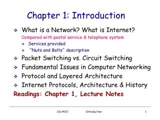
Chapter 1: Introduction
Our goal: get context, overview, “feel” of networking more depth, detail later in course approach: descriptive use Internet as example. Overview: what’s the Internet what’s a protocol? network edge network core access net, physical media Internet/ISP structure

Chapter 1: Introduction
E N D
Presentation Transcript
Our goal: get context, overview, “feel” of networking more depth, detail later in course approach: descriptive use Internet as example Overview: what’s the Internet what’s a protocol? network edge network core access net, physical media Internet/ISP structure performance: loss, delay protocol layers, service models history Chapter 1: Introduction Introduction
Chapter 1: roadmap 1.1 What is the Internet? 1.2 Network edge 1.3 Network core 1.4 Network access and physical media 1.5 Internet structure and ISPs 1.6 Delay & loss in packet-switched networks 1.7 Protocol layers, service models 1.8 History Introduction
millions of connected computing devices: hosts, end-systems PCs workstations, servers PDAs phones, toasters running network apps communication links fiber, copper, radio, satellite transmission rate = bandwidth routers: forward packets (chunks of data) router workstation server mobile local ISP regional ISP company network What’s the Internet: “nuts and bolts” view Introduction
“Cool” internet appliances IP picture frame http://www.ceiva.com/ Web-enabled toaster+weather forecaster World’s smallest web server http://www-ccs.cs.umass.edu/~shri/iPic.html Introduction
protocolscontrol sending, receiving of msgs e.g., TCP, IP, HTTP, FTP, PPP Internet: “network of networks” loosely hierarchical public Internet versus private intranet Internet standards RFC: Request for comments IETF: Internet Engineering Task Force What’s the Internet: “nuts and bolts” view router workstation server mobile local ISP regional ISP company network Introduction
communication infrastructure enables distributed applications: Web, email, games, e-commerce, database., voting, file (MP3) sharing communication services provided to apps: connectionless connection-oriented What’s the Internet: a service view • cyberspace [Gibson]: “a consensual hallucination experienced daily by billions of operators, in every nation, ...." Introduction
human protocols: “what’s the time?” “I have a question” introductions … specific msgs sent … specific actions taken when msgs received, or other events network protocols: machines rather than humans all communication activity in Internet governed by protocols What’s a protocol? protocols define format, order of msgs sent and received among network entities, and actions taken on msg transmission, receipt Introduction
a human protocol and a computer network protocol: TCP connection response Get http://www.awl.com/kurose-ross Got the time? 2:00 <file> time What’s a protocol? Hi TCP connection req Hi Q: Other human protocols? Introduction
network edge: applications and hosts network core: routers network of networks access networks, physical media: communication links A closer look at network structure: Introduction
Chapter 1: roadmap 1.1 What is the Internet? 1.2 Network edge 1.3 Network core 1.4 Network access and physical media 1.5 Internet structure and ISPs 1.6 Delay & loss in packet-switched networks 1.7 Protocol layers, service models 1.8 History Introduction
end systems (hosts): run application programs e.g. Web, email at “edge of network” client/server model client host requests, receives service from always-on server e.g. Web browser/server; email client/server peer-peer model: minimal (or no) use of dedicated servers e.g. Gnutella, KaZaA The network edge: Introduction
Goal: data transfer between end systems handshaking: setup (prepare for) data transfer ahead of time Hello, hello back human protocol set up “state” in two communicating hosts TCP - Transmission Control Protocol Internet’s connection-oriented service TCP service[RFC 793] reliable, in-order byte-stream data transfer loss: acknowledgements and retransmissions flow control: sender won’t overwhelm receiver congestion control: senders “slow down sending rate” when network congested Network edge: connection-oriented service Introduction
Goal: data transfer between end systems same as before! UDP - User Datagram Protocol [RFC 768]: Internet’s connectionless service unreliable data transfer no flow control no congestion control App’s using TCP: HTTP (Web), FTP (file transfer), Telnet (remote login), SMTP (email) App’s using UDP: streaming media, teleconferencing, DNS, Internet telephony Network edge: connectionless service Introduction
Chapter 1: roadmap 1.1 What is the Internet? 1.2 Network edge 1.3 Network core 1.4 Network access and physical media 1.5 Internet structure and ISPs 1.6 Delay & loss in packet-switched networks 1.7 Protocol layers, service models 1.8 History Introduction
mesh of interconnected routers the fundamental question: how is data transferred through net? circuit switching: dedicated circuit per call: telephone net packet-switching: data sent thru net in discrete “chunks” The Network Core Introduction
End-end resources reserved for “call” link bandwidth, switch capacity dedicated resources: no sharing circuit-like (guaranteed) performance call setup required Network Core: Circuit Switching Introduction
network resources (e.g., bandwidth) divided into “pieces” pieces allocated to calls resource piece idle if not used by owning call (no sharing) Network Core: Circuit Switching • dividing link bandwidth into “pieces” • frequency division • time division Introduction
Example: 4 users FDMA frequency time TDMA frequency time Circuit Switching: TDMA and TDMA Introduction
each end-end data stream divided into packets user A, B packets share network resources each packet uses full link bandwidth resources used as needed Bandwidth division into “pieces” Dedicated allocation Resource reservation Network Core: Packet Switching resource contention: • aggregate resource demand can exceed amount available • congestion: packets queue, wait for link use • store and forward: packets move one hop at a time • transmit over link • wait turn at next link Introduction
Sequence of A & B packets does not have fixed pattern statistical multiplexing. In TDM each host gets same slot in revolving TDM frame. D E Packet Switching: Statistical Multiplexing 10 Mbs Ethernet C A statistical multiplexing 1.5 Mbs B queue of packets waiting for output link Introduction
1 Mbit link each user: 100 kbps when “active” active 10% of time circuit-switching: 10 users packet switching: with 35 users, probability > 10 active less than .0004 Packet switching allows more users to use network! Packet switching versus circuit switching N users 1 Mbps link Introduction
Great for bursty data resource sharing simpler, no call setup Excessive congestion: packet delay and loss protocols needed for reliable data transfer, congestion control Q: How to provide circuit-like behavior? bandwidth guarantees needed for audio/video apps still an unsolved problem (chapter 6) Is packet switching a “slam dunk winner?” Packet switching versus circuit switching Introduction
Takes L/R seconds to transmit (push out) packet of L bits on to link or R bps Entire packet must arrive at router before it can be transmitted on next link: store and forward delay = 3L/R Example: L = 7.5 Mbits R = 1.5 Mbps delay = 15 sec Packet-switching: store-and-forward L R R R Introduction
Now break up the message into 5000 packets Packet Switching: Message Segmenting • Each packet 1,500 bits • 1 msec to transmit packet on one link • pipelining: each link works in parallel • Delay reduced from 15 sec to 5.002 sec Introduction
Goal: move packets through routers from source to destination we’ll study several path selection (i.e. routing)algorithms (chapter 4) datagram network: destination address in packet determines next hop routes may change during session analogy: driving, asking directions virtual circuit network: each packet carries tag (virtual circuit ID), tag determines next hop fixed path determined at call setup time, remains fixed thru call routers maintainper-call state Packet-switched networks: forwarding Introduction
Packet-switched networks Circuit-switched networks FDM TDM Datagram Networks Networks with VCs Network Taxonomy Telecommunication networks • Datagram network is not either connection-oriented • or connectionless. • Internet provides both connection-oriented (TCP) and • connectionless services (UDP) to apps. Introduction
Chapter 1: roadmap 1.1 What is the Internet? 1.2 Network edge 1.3 Network core 1.4 Network access and physical media 1.5 Internet structure and ISPs 1.6 Delay & loss in packet-switched networks 1.7 Protocol layers, service models 1.8 History Introduction
Q: How to connection end systems to edge router? residential access nets institutional access networks (school, company) mobile access networks Keep in mind: bandwidth (bits per second) of access network? shared or dedicated? Access networks and physical media Introduction
Dialup via modem up to 56Kbps direct access to router (often less) Can’t surf and phone at same time: can’t be “always on” Residential access: point to point access • ADSL: asymmetric digital subscriber line • up to 1 Mbps upstream (today typically < 256 kbps) • up to 8 Mbps downstream (today typically < 1 Mbps) • FDM: 50 kHz - 1 MHz for downstream 4 kHz - 50 kHz for upstream 0 kHz - 4 kHz for ordinary telephone Introduction
HFC: hybrid fiber coax asymmetric: up to 10Mbps upstream, 1 Mbps downstream network of cable and fiber attaches homes to ISP router shared access to router among home issues: congestion, dimensioning deployment: available via cable companies, e.g., MediaOne Residential access: cable modems Introduction
Residential access: cable modems Diagram: http://www.cabledatacomnews.com/cmic/diagram.html Introduction
Cable Network Architecture: Overview Typically 500 to 5,000 homes cable headend home cable distribution network (simplified) Introduction
Cable Network Architecture: Overview cable headend home cable distribution network (simplified) Introduction
server(s) Cable Network Architecture: Overview cable headend home cable distribution network Introduction
C O N T R O L D A T A D A T A V I D E O V I D E O V I D E O V I D E O V I D E O V I D E O 5 6 7 8 9 1 2 3 4 Channels Cable Network Architecture: Overview FDM: cable headend home cable distribution network Introduction
company/univ local area network (LAN) connects end system to edge router Ethernet: shared or dedicated link connects end system and router 10 Mbs, 100Mbps, Gigabit Ethernet deployment: institutions, home LANs happening now LANs: chapter 5 Company access: local area networks Introduction
shared wireless access network connects end system to router via base station aka “access point” wireless LANs: 802.11b (WiFi): 11 Mbps wider-area wireless access provided by telco operator 3G ~ 384 kbps Will it happen?? WAP/GPRS in Europe router base station mobile hosts Wireless access networks Introduction
Typical home network components: ADSL or cable modem router/firewall/NAT Ethernet wireless access point Home networks wireless laptops to/from cable headend cable modem router/ firewall wireless access point Ethernet (switched) Introduction
Bit: propagates betweentransmitter/rcvr pairs physical link: what lies between transmitter & receiver guided media: signals propagate in solid media: copper, fiber, coax unguided media: signals propagate freely, e.g., radio Twisted Pair (TP) two insulated copper wires Category 3: traditional phone wires, 10 Mbps Ethernet Category 5 TP: 100Mbps Ethernet Physical Media Introduction
Coaxial cable: two concentric copper conductors bidirectional baseband: single channel on cable legacy Ethernet broadband: multiple channel on cable HFC Physical Media: coax, fiber Fiber optic cable: • glass fiber carrying light pulses, each pulse a bit • high-speed operation: • high-speed point-to-point transmission (e.g., 5 Gps) • low error rate: repeaters spaced far apart ; immune to electromagnetic noise Introduction
signal carried in electromagnetic spectrum no physical “wire” bidirectional propagation environment effects: reflection obstruction by objects interference Physical media: radio Radio link types: • terrestrial microwave • e.g. up to 45 Mbps channels • LAN (e.g., WaveLAN) • 2Mbps, 11Mbps • wide-area (e.g., cellular) • e.g. 3G: hundreds of kbps • satellite • up to 50Mbps channel (or multiple smaller channels) • 270 msec end-end delay • geosynchronous versus LEOS Introduction
Chapter 1: roadmap 1.1 What is the Internet? 1.2 Network edge 1.3 Network core 1.4 Network access and physical media 1.5 Internet structure and ISPs 1.6 Delay & loss in packet-switched networks 1.7 Protocol layers, service models 1.8 History Introduction
roughly hierarchical at center: “tier-1” ISPs (e.g., UUNet, BBN/Genuity, Sprint, AT&T), national/international coverage treat each other as equals NAP Tier-1 providers also interconnect at public network access points (NAPs) Tier-1 providers interconnect (peer) privately Internet structure: network of networks Tier 1 ISP Tier 1 ISP Tier 1 ISP Introduction
Tier-1 ISP: e.g., Sprint Sprint US backbone network Introduction
“Tier-2” ISPs: smaller (often regional) ISPs Connect to one or more tier-1 ISPs, possibly other tier-2 ISPs NAP Tier-2 ISPs also peer privately with each other, interconnect at NAP • Tier-2 ISP pays tier-1 ISP for connectivity to rest of Internet • tier-2 ISP is customer of tier-1 provider Tier-2 ISP Tier-2 ISP Tier-2 ISP Tier-2 ISP Tier-2 ISP Internet structure: network of networks Tier 1 ISP Tier 1 ISP Tier 1 ISP Introduction
“Tier-3” ISPs and local ISPs last hop (“access”) network (closest to end systems) Tier 3 ISP local ISP local ISP local ISP local ISP local ISP local ISP local ISP local ISP NAP Local and tier- 3 ISPs are customers of higher tier ISPs connecting them to rest of Internet Tier-2 ISP Tier-2 ISP Tier-2 ISP Tier-2 ISP Tier-2 ISP Internet structure: network of networks Tier 1 ISP Tier 1 ISP Tier 1 ISP Introduction
a packet passes through many networks! Tier 3 ISP local ISP local ISP local ISP local ISP local ISP local ISP local ISP local ISP NAP Tier-2 ISP Tier-2 ISP Tier-2 ISP Tier-2 ISP Tier-2 ISP Internet structure: network of networks Tier 1 ISP Tier 1 ISP Tier 1 ISP Introduction
Chapter 1: roadmap 1.1 What is the Internet? 1.2 Network edge 1.3 Network core 1.4 Network access and physical media 1.5 Internet structure and ISPs 1.6 Delay & loss in packet-switched networks 1.7 Protocol layers, service models 1.8 History Introduction
packets queue in router buffers packet arrival rate to link exceeds output link capacity packets queue, wait for turn packet being transmitted (delay) packets queueing (delay) free (available) buffers: arriving packets dropped (loss) if no free buffers How do loss and delay occur? A B Introduction
1. nodal processing: check bit errors determine output link transmission A propagation B nodal processing queueing Four sources of packet delay • 2. queueing • time waiting at output link for transmission • depends on congestion level of router Introduction