Streaming Readout DAQ System for BDX Experiment: Design and Implementation Overview
This presentation outlines the design and implementation of a streaming readout Data Acquisition System (DAQ) tailored for the BDX experiment. It details the DAQ architecture, featuring a trigger-less front-end system adapted from the KM3NeT experiment, and highlights the key components, including the digitizer board with low-power ADCs, high voltage provisions for sensors, and innovative event building techniques. Key performance metrics such as signal thresholds, timing properties, and scalability are also discussed, demonstrating the DAQ’s effectiveness in high-light yield environments.

Streaming Readout DAQ System for BDX Experiment: Design and Implementation Overview
E N D
Presentation Transcript
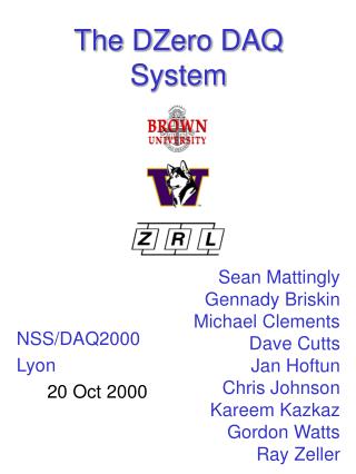
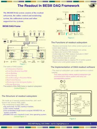
A streaming readout DAQ system for the BDX experiment Fabrizio Ameli INFN - ROMA
Outline • BDX experiment requirements • Streaming Readout DAQ • The Digitizer Board • Description • Characterization • Trigger architecture • Conclusions • Trigger-less benefits fabrizio.ameli@roma1.infn.it @ IV SRO WORKSHOP
The Beam Dump eXperiment • High light yield of searched events • ~5 phe threshold • SiPM noise is under threshold • hit amplitude is O(100 mV) • Hit timing properties: • duration: O(10 ms) • bandwidth: O(10 MHz) • rate @ 5 phe threshold: O(10 Hz) Remember L. Marsicano talk fabrizio.ameli@roma1.infn.it @ IV SRO WORKSHOP
From front-end to DAQ • DAQ architecture and front-end inherited from KM3NeT experiment: • Trigger-less front-end system: • ADC sampling (14 bit, 200MHz 250MHz) • zero-suppression (L0 trigger) @ 0.3 p.e. threshold • sampling window is time-variable • all non-zero data forwarded (all data to shore) • Trigger-less Data Acquisition System (TriDAS) • Scalable Event Building architecture • DAQ scalability relies on network scalability 23 May 2019 fabrizio.ameli@roma1.infn.it @ IV SRO WORKSHOP
From front-end to DAQ See T. Chiarusi talk • DAQ architecture and front-end inherited from KM3NeT experiment: • Trigger-less front-end system: • ADC sampling (14 bit, 200MHz 250MHz) • zero-suppression (L0 trigger) @ 0.3 p.e. threshold • sampling window is time-variable • all non-zero data forwarded (streaming-like data flow) • Trigger-less Data Acquisition System (TriDAS) • Scalable Event Building architecture • DAQ scalability relies on network scalability 23 May 2019 fabrizio.ameli@roma1.infn.it @ IV SRO WORKSHOP
The WaveBoard digitizer board Single Channel Front Endw/ High Voltage • The board is based on a Commercial-Off-The-Shelf (COTS) System On Module (SOM) mezzanine card hosting a Zynq-7030 • There are 12 analog front end channels • 6 dual-channel ultra low-power ADCs (12/14 bit up to 250MHz) • Pre-amplifier on board: selectable gain (either 2 or 50) • HV provided and monitored on-board • pedestal set by DAC • Timing interfaces: • PLL to clean, generate, and distribute clocks • External clock and reference signals • White Rabbit enabled board • ARM-M4 controls on-board peripherals (ADCs, DACs, PLL, …) • On board peripherals: • High speed: GbE, SFP, USB OTG • Low Speed: serial, I2C, temperature monitor fabrizio.ameli@roma1.infn.it @ IV SRO WORKSHOP
Trenz Electronics - TE0745 – Pluggable SOM • K7-Based Zynq • Zynq-7030/7035/7045 • DC/DC onboard • 1GB DDR3 • 32 MB SPI Flash • 1 Gb Ethernet PHY • USB 2.0 PHY • I2C, RTC, EEPROM (MAC) • 250 I/O pins + 6 MIO • I/O banks power from connector 7.6 cm 5.2 cm fabrizio.ameli@roma1.infn.it @ IV SRO WORKSHOP
Board features: Interfaces SAMTEC HS Connector SATA • High Speed interfaces: • 1 x GbE connector (PS driven) • 1 x SFP connector (PL driven) • 3 SATA connectors • 1 x USB On The Go • High Speed Samtec expansion connector • Boards can be easily daisy chained using FPGA MGTs on SATA connectors. • Low speed interfaces: • 2 serial ports • 1 I2C bus • 1 USB • 1 daisy chainabletemperature sensor SFP E/O 1 GbE fabrizio.ameli@roma1.infn.it @ IV SRO WORKSHOP
Board features: Power Analog Supplies (+5V, -5V) 1.8V FastADC Linear Regulator • Linear regulators dedicated to analog front-end supplies (+5V and -5V) • Dedicated 1.8V linear regulator per FastADC • VME connectors only for power and mechanical support • SiPM High Voltage up to 90V provided on-board • Power consumption: • 2.3A @5V • 0.5A @ 12V • Total power ~17.5 W Digital Supplies (1.8V, 3.3V) fabrizio.ameli@roma1.infn.it @ IV SRO WORKSHOP
Board Cost • Board cost is adjustable according to project requirements: • Use the right ADC: price ranges from 9 to 65 €/channel • Choose the right SOM: 500€ to 780€ • Total cost ranges from 1.3k€ to 2.1k€ per board fabrizio.ameli@roma1.infn.it @ IV SRO WORKSHOP
Digitization example: BDX crystal read by SiPM DAQ Setup Procedure • Set over and under thresholds • Set Leading samples number • Set Trailing samples number Acquisition Process • Time stamp is set on first over threshold sample • A packet with channel ID, charge, time stamp and samples is pushed through Ethernet interface • Dead time happens when output link speed is too low wrt hit rate ADC Counts Time (4 ns units) fabrizio.ameli@roma1.infn.it @ IV SRO WORKSHOP
High Voltage set and measurement • The board can provide High Voltage to power sensors (typically SiPM) • HV is AC-coupled to sensor signal • up to 90V on-board generation • HV is linearly regulated (accepted input up to 100V) • Range is from 25 to 75V, DAC selectable • Changing HW configuration, the same circuit can control a HV generator (e.g. PMT HV base can be set by a control voltage ranging from 0 to 2V) fabrizio.ameli@roma1.infn.it @ IV SRO WORKSHOP
High Voltage set and measurement • High Voltage set to 25V: • Values read by Voltmeter and on-board ADC • Channel average error: 0.2% fabrizio.ameli@roma1.infn.it @ IV SRO WORKSHOP
High Voltage set and measurement • High Voltage set to 75V: • Values read by Voltmeter and on-board ADC • Channel average error: 0.7% fabrizio.ameli@roma1.infn.it @ IV SRO WORKSHOP
High Voltage set and measurement • High Voltage set to 75V: • Values read by Voltmeter and on-board ADC • Channel average error: 0.7% Gain Correction Factor: 1.01 fabrizio.ameli@roma1.infn.it @ IV SRO WORKSHOP
Pedestal estimation and Noise • Channel Pedestal estimate: 1.6-1.9 ADC count (rms) • Calculated on 105 samples • Input is Open • No HV generated fabrizio.ameli@roma1.infn.it @ IV SRO WORKSHOP
Pedestal estimation and Noise • Channel Pedestal estimate: 2.2-2.6 ADC count (rms) • Calculated on 105 samples • Input is Open • HV generated fabrizio.ameli@roma1.infn.it @ IV SRO WORKSHOP
Timing test bench setup: clock quality RIGOL DG5052 10 MHz Gen VME Crate w/ Board UT E5052B SSA Input clock from generator: 10 MHz Input clock is jitter-cleaned and multiplied by a factor 25 by on-board PLL Jitter performance measured with E5052B-Signal Source Analyzer fabrizio.ameli@roma1.infn.it @ IV SRO WORKSHOP
Timing test bench setup: clock quality Carrier:249.99… MHz -20 dBC/Hz 20 dB/div Tek DTG21/RIGOL DG5052 RMS Jitter:518.14 fs 10 MHz Clock 250 MHz Clock -180 dBC/Hz Board#0 Board#1 Board#2 Input clock from generator: 10 MHz Input clock is jitter-cleaned and multiplied by a factor 25 by on-board PLL Jitter performance measured with E5052B-Signal Source Analyzer fabrizio.ameli@roma1.infn.it @ IV SRO WORKSHOP
Timing test bench setup: resolution Calibration Pulses ADC Counts Threshold Time (4 ns units) • Input is driven by a pulse generator (DTG5334) • Pulses period: 50 kHz • Histogram of time differences between consecutive pulses • Linear interpolation of waveforms • The higher the amplitude, the better • Spline interpolation enhances resolution fabrizio.ameli@roma1.infn.it @ IV SRO WORKSHOP
Timing test bench setup: resolution Counts Threshold Time difference • Input is driven by a pulse generator (DTG5334) • Pulses period: 50 kHz • Histogram of time differences between consecutive pulses • Linear interpolation of waveforms • The higher the amplitude, the better • Spline interpolation enhances resolution fabrizio.ameli@roma1.infn.it @ IV SRO WORKSHOP
Triggered architecture HW PC Data Flow • HW Trigger: • Signal feature extraction • Stream few data forward • If level2 triggers: send all data forward • Buffering: • Enough to cope with trigger latency • Detector sectioning: • Needed to implement local triggers • Event Selection: • Higher trigger levels fabrizio.ameli@roma1.infn.it @ IV SRO WORKSHOP
Streaming Readout architecture Time Slice 1 0 2 3 1 t(s) HW PC Data Flow • HW DAQ: • L0 trigger (Zero Skipping) • Stream all data forward • Buffering: • Enough to cope with transmission link • Detector sectioning: • Not needed • Event Selection: • Time is divided into time slices • Hits in the same time slice are forwarded to same trigger PC fabrizio.ameli@roma1.infn.it @ IV SRO WORKSHOP
Streaming Readout architecture Time Slice 2 0 2 3 1 t(s) HW PC Data Flow • HW DAQ: • L0 trigger (Zero Skipping) • Stream all data forward • Buffering: • Enough to cope with transmission link • Detector sectioning: • Not needed • Event Selection: • Time is divided into time slices • Hits in the same time slice are forwarded to same trigger PC fabrizio.ameli@roma1.infn.it @ IV SRO WORKSHOP
Streaming Readout architecture Time Slice 3 0 2 3 1 t(s) HW PC Data Flow • HW DAQ: • L0 trigger (Zero Skipping) • Stream all data forward • Buffering: • Enough to cope with transmission link • Detector sectioning: • Not needed • Event Selection: • Time is divided into time slices • Hits in the same time slice are forwarded to same trigger PC fabrizio.ameli@roma1.infn.it @ IV SRO WORKSHOP
Streaming Readout architecture Time Slice 4 0 2 3 1 t(s) HW PC Data Flow • HW DAQ: • L0 trigger (Zero Skipping) • Stream all data forward • Buffering: • Enough to cope with transmission link • Detector sectioning: • Not needed • Event Selection: • Time is divided into time slices • Hits in the same time slice are forwarded to same trigger PC fabrizio.ameli@roma1.infn.it @ IV SRO WORKSHOP
Streaming Readout architecture Time Slice 4 0 2 3 1 t(s) HW PC Data Flow • HW DAQ: • L0 trigger (Zero Skipping) • Stream all data forward • Buffering: • Enough to cope with transmission link • Detector sectioning: • Not needed • Event Selection: • Time is divided into time slices • Hits in the same time slice are forwarded to same trigger PC fabrizio.ameli@roma1.infn.it @ IV SRO WORKSHOP
Streaming readout: cons • Less efficient in terms of total data rates • HW could be more demanding • In some cases, data rates are so high that pushing all data is not feasible • If L0 discards data (ie hit is under threshold), data are lost! • If triggered systems apply L0, both approaches are equivalent fabrizio.ameli@roma1.infn.it @ IV SRO WORKSHOP
Streaming readout: HW benefits • Flat Front End nodes hierarchy • FE nodes are independent from each other • Same minimal HW programming required for all nodes (no trigger, no feature extraction, no strict latency) • Unidirectional data flow • Changing trigger doesn’t change HW • Connecting network should be based on commercial protocols/HW: • Ethernet network: low cost, wide availability, FPGA IP core support • Ethernet switches can be used as data concentrator fabrizio.ameli@roma1.infn.it @ IV SRO WORKSHOP
Streaming readout: DAQ benefits • Trigger algorithm complexity moves into SW domain • Trigger algorithms can be applied to the whole detector • The architecture is scalable as long as the network is: • If trigger algorithm gets more and more complex, just add PCs • If FE rate gets higher (eg using lower thresholds), just add PCs • If FE nodes grow, just add more PCs fabrizio.ameli@roma1.infn.it @ IV SRO WORKSHOP
BDX status • Beam Dump eXperimentat JLab:search for Dark sector particlesin the 1 ÷ 1000 MeV mass range. • High intensity (≃ 1022EOT/year), high energy (11GeV) e- beam • Detector: ~800 CsI(Tl) calorimeter + 2-layers active veto + shielding.Reuse BaBar crystals with improved SiPM readout. • BDX can be ready to run within ~2 years • Current experiment status: • Full proposal submitted to JLab PAC 44: conditionally approved • After PAC45 update, on-site background measurements and detector optimization studies • Presented update to PAC46 for approval fabrizio.ameli@roma1.infn.it @ IV SRO WORKSHOP
Timing: test bench setup Carrier:9.999995 MHz -20 dBC/Hz 20 dB/div Tek DTG21/RIGOL DG5052 RMS Jitter:8.2 ps 10 MHz Clock E5052B Signal Source Analyzer 250 MHz Clock -180 dBC/Hz Board#0 Board#1 Board#2 Ref 10 MHz clock path:Generator Clock JItter fabrizio.ameli@roma1.infn.it @ IV SRO WORKSHOP
Board features: Power • Linear regulators dedicated to analog front-end supplies (+5V and -5V) • Dedicated 1.8V linear regulator per FastADC • VME connectors only for power and mechanical support • SiPM High Voltage up to 90V provided on-board • Power consumption: • 2.3A @5V • 0.5A @ 12V • Total power ~17.5 W fabrizio.ameli@roma1.infn.it @ IV SRO WORKSHOP
Programmable Logic DDR DMA AFE #1 AFE #2 PS ARM-A9 AFE #3 1 GbE AFE #12 fabrizio.ameli@roma1.infn.it @ IV SRO WORKSHOP