Download
1 / 1
10 likes | 119 Vues
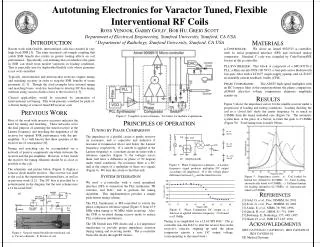
This work presents a push-of-a-button tuning method for varactor tuned RF receiver coils, enabling quick adjustment for optimal performance in interventional procedures. The system integrates a μ-controller, PLL synthesizer, and phase comparator to automate the tuning process. Impedance curves demonstrate the system's ability to maintain peak performance under varying loading conditions. Previous research underscores the importance of tuning and matching for maximizing SNR benefits in interventional coil designs. Principles of operation and results from experimental impedance tuning are detailed.

E N D
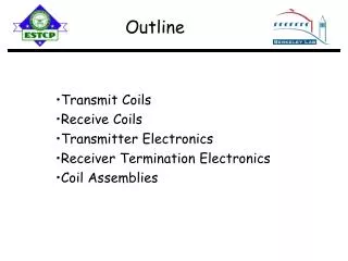
manual tune 9 V 10K DC bias, RF isolate C 8 F->0 Vo>0 150pF 20K 20K 75nH Va Cref Flex coil _ + 22 or 68pF Rcv Reference signal + Q spoil F->90 Vo=0 <360nH Varactor Vo Port Vb _ Filter C 8 Pull wire coil F->180 Vo<0 ~15 cm 2.5 cm 2 turns Vo ~ |Va||Vb|cos(Φ) a) Autotuning Electronics for Varactor Tuned, Flexible Interventional RF Coils ROSS VENOOK, GARRY GOLD†, BOB HU, GREIG SCOTT Department of Electrical Engineering, Stanford University, Stanford, CA USA † Department of Radiology, Stanford University, Stanford, CA USA INTRODUCTION MATERIALS Recent work with flexible, interventional coils has resulted in very high local SNR [1]. The same increased coil-sample coupling that yields SNR benefit also results in greater loading effects on coil performance. Specifically, coil detuning that overshadows the gains in SNR can result from modest variations in loading conditions. This is especially true for deployable/flexible coils whose geometry is not well controlled. Typically, interventional and intravascular receivers require tuning and matching circuitry in order to reap the SNR benefits of tissue proximity [2, 3]. Though the cited examples have external tuning and matching boxes, work has been done to develop DC-bias tuning methods using varactor diodes closer to the receiver [4, 5]. Clinical applicability would be increased by automation of interventional coil tuning. This work presents a method for push-of-a-button tuning of varactor tuned RF receiver coils. μ-CONTROLLER: We chose an Atmel 9028515 μ-controller, with its serial peripheral interface (SPI) and on-board analog comparator. Standard C code was compiled by CodeVisionAVR for use in the μ-controller. PLL SYNTHESIZER: This block is composed of a MC145170-2 PLL, a Mini-circuits POS-100 VCO, a four-pole active Butterworth low-pass filter with a LT1677 single-supply opamp, and a LT1227 tri-stateable current feedback buffer (CFB). PHASE COMPARATOR: The AD835 high speed multiplier with an RC lowpass filter at the output performs the phase comparison. AD9665 ultra-fast voltage comparators eliminate amplitude sensitivity. RESULTS Figure 5 shows the impedance curves for the tunable receiver under a progression of loading and tuning conditions. Loading (holding the coil in a closed fist) shifts the center frequency by as much as 2.8MHz from the tuned, unloaded case (Figure 5a). The automatic system then, at the press of a button, re-tunes the peak to 63.8MHz (Figure 5b). Total tuning time is under 300ms. PREVIOUS WORK Figure 2: Complete system schematic. See below for modular explanations. Most of the work with invasive receivers indicates the need for tuning and matching. These networks serve the dual purpose of centering the tuned receiver at the Larmor frequency and matching the impedance of the receiver for optimal SNR performance with the pre-amplifier. It is well known that these qualities of the receiver are of consequence [6]. Tuning and matching can be accomplished via a network of passive components anywhere between the receiver and the pre-amplifier. However, to best match the receiver, the tuning elements should be as close as possible to the coil. The schematic and picture below (Figure 1) display a varactor diode tunable receiver. This receiver was used as the coil in the experiments presented here, as well as in previous work [1,2]. The DC bias is provided by a potentiometer in the diagram, but the new scheme uses a 12 bit serial DAC. PRINCIPLES OF OPERATION TUNING BY PHASE COMPARISON The impedance of a parallel circuit is purely resistive on resonance, and is capacitive and inductive if resonant at frequencies above and below the Larmor frequency, respectively. If a current is applied at the Larmor frequency to a resonant circuit in series with a reference capacitor (Figure 3), the voltages across them will have a difference in phase of 90 degrees under tuned conditions. On resonance there is a DC null at the output of a multiplier of these two signals (Figure 4). We tune the circuit to find this null. Figure 3: Phase Comparator schematic. A Larmor frequency signal produces multiplier DC output according coil impedance. Φ is the voltage phase difference between Cref and the tuned receiver. SYSTEM INTEGRATION Figure 5: Impedance curves. a) Coil loaded by human fist, detuned to 66.6MHz. b) Same loading, automatically tuned to 63.8MHz. c) Different human fist loading, detuned to 62.55MHz. d) Automatically tuned to 63.8MHz. We used a μ-controller with a serial peripheral interface (SPI) to orchestrate the PLL synthesizer, TR switches, and DAC, and to perform the tuning algorithm. This implementation provides a simple push-button tuning scheme. The PLL Synthesizer is SPI-controlled to switch the phase comparator reference signal (Figure 3) from 63.9 MHz when tuning to 90 MHz while receiving. Also, the CFB is tri-stated during receive mode to reduce PLL synthesizer interference. The TR Switch uses PIN diodes and a λ/4 impedance transformer to provide proper impedance isolation during tuning and receiving modes. The μ-controller biases the diodes through RF chokes. REFERENCES [1] Gold, G. et al., Proc. ISMRM, 84, 2001. [2] Scott, G. et al., Proc. ISMRM, 20, 2001. [3] Atalar, E. et al., MRM, 36: 596, 1996. [4] Quick, H. et al., MRM, 41: 751, 1999. [5] Boskamp, E., Radiology, 157: 449, 1985. [5] Hoult, D. et al., JMR 24:71-85, 1976. Figure 4: Phase Comparator DC output as a function of applied reference frequency. Coil tuned to 63.9MHz. Tuning is accomplished via a 12-bit SPI DAC. The μ-controller uses the DAC to alter the reverse bias on the receiver’s varactor, stepping up until the phase comparator reports a zero DC output voltage. (corresponding to the tuned state.) ACKNOWLEDGMENTS NIH: CA79728-01; CA95882-01; 1R01 CA92409-01 1R24 CA92862-01 GE Medical Systems Figure 1: Varactor tuned flexible interventional coil. a) Circuit schematic. b) Picture of coil.