Download
1 / 41
430 likes | 645 Vues
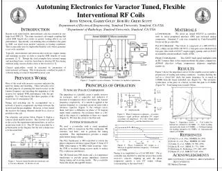
Autotuning Electronics for Varactor Tuned, Flexible Interventional RF Coils. Ross Venook, Greig Scott, Garry Gold, and Bob Hu. Introduction. Basics of Magnetic Resonance Imaging (MRI) Motivation Why use interventional coils? Why is this hard? Background History RF coil tuning method(s)

E N D
Autotuning Electronics for Varactor Tuned, Flexible Interventional RF Coils Ross Venook, Greig Scott, Garry Gold, and Bob Hu
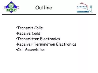
Introduction • Basics of Magnetic Resonance Imaging (MRI) • Motivation • Why use interventional coils? • Why is this hard? • Background • History • RF coil tuning method(s) • What we tried • Modular electronics discussion • Results • Next steps
z y x The First Thing About MRI • Bloch Equation: ω = γB • ω : precession/Larmor frequency • γ : gyromagnetic ratio (2π•42.575MHz/Tesla) • B : local magnetic field strength (Tesla) Hydrogen atom “spin” B ω B
z z z y y y x x x The Second Thing About MRI Before RF Excitation RF Excitation RF Relaxation • During relaxation, the spins emit EM radiation at ω = γBlocal • RF coil inductively couples this signal “Tip” B ω Transverse component
Bfinal By-gradient z + = y x Signal ωo ω Object Relaxation Signal (freq. domain) Simple Example Bo • Linear gradient produces frequency encoding of spatial hydrogen atom distribution
Other Important Points • Signal to Noise Ratio (SNR) is the figure of merit for MRI • SNR acts as a currency for other MRI attributes (resolution, field of view, scan time) • Clinically-driven field • Focus on medical problems/solutions • Factors of two matter • Primary advantage of MRI: it is a non-invasive imaging modality
Why Use Interventional Coils? • Increased signal coupling & reduced noise coupling better SNR Coupled noise Coupled signal
Applications: Existing and Potential • Existing • Intravascular coils • Endorectal coils • Potential • Inter-articular • <add your application here>
Why Interventional Coils Are Harder to Use: Dynamic loading • Proximity works both ways • Closer coupling also means greater local tissue dependency • Requires deployability in some applications • Scaling works both ways • Human-scale effects are significant • Geometry more important
So… • Dynamic loading conditions require dynamic tuning to maximize SNR advantages with interventional coils • The tuning process should be automatic, and must add neither noise nor interference to the acquired signal
3” surface coil (GE) “RF Coils” • RF transmitters and receivers (in MR) are magnetic field coupling resonators that are tuned to the Larmor frequency • Examples: • Saddle • Surface • Interventional
Resonance • ‘Parallel RLC’ circuit • Governing equation • Familiar result
60 30 50 20 40 10 Reactance [Ohms] Resistance [Ohms] 30 0 20 -10 10 -20 0 -30 50 55 60 65 70 75 50 55 60 65 70 75 Frequency [MHz] Frequency [MHz] Impedance of Resonant Circuits
Goals: Tuning and Matching • Tuning • Center Frequency near Larmor • Bandwidth appropriate to application • Matching • Tuned impedance near 50 + j0 ohms
Complications • Loading the coil with a sample necessarily creates coupling (it better!) • Dynamic coupling creates dynamic tuning/matching conditions
Tuned Detuned
History • Tuning MRI coils (Boskamp 1985) • Automatic Tuning and Matching (Hwang and Hoult, 1998) • IV Expandable Loop Coils (Martin, et al, 1996)
Shoulders • Varactor Tuned Flexible Interventional Receiver Coils (Scott and Gold, ISMRM 2001) Cadaver Shoulder, 1.5T 3D/SPGR/20 slices 6cm FOV, 512x512
manual tune 9 V 10K DC bias, RF isolate 150pF 20K 20K 75nH Flex coil 22 or 68pF Rcv Q spoil <360nH Varactor Port C C 8 8 Pull wire ~15 cm 2.5 cm 2 turns Greig’s Tunable Coil
Basic Tuning Method • Manually change DC bias on varactor • Maximize magnitude response • FID is a reasonable measure Drawbacks: • Requires manual iterative approach • Maximum FID may not correspond to maximum SNR • Feedback not effective with maximization
60 30 50 20 40 10 Reactance [Ohms] Resistance [Ohms] 30 0 20 -10 10 -20 0 -30 50 55 60 65 70 75 50 55 60 65 70 75 Frequency [MHz] Frequency [MHz] A Better Method Using Phase • Zero-crossing at resonant frequency
60 50 40 Resistance [Ohms] Reactance [Ohms] 30 20 10 30 30 30 0 50 55 60 65 70 75 50 55 60 65 70 75 Frequency [MHz] Frequency [MHz] 20 20 20 60 50 10 10 10 40 Resistance [Ohms] Reactance [Ohms] 30 0 0 0 20 10 -10 -10 -10 0 50 55 60 65 70 75 50 55 60 65 70 75 Frequency [MHz] Frequency [MHz] -20 -20 -20 60 50 40 Resistance [Ohms] Reactance [Ohms] 30 20 10 0 50 55 60 65 70 75 50 55 60 65 70 75 Frequency [MHz] Frequency [MHz] At 63.9MHz
F->0 Vo>0 Va Cref _ + + F->90 Vo=0 Signal source Vo Vb _ AD835 250 MHz Multiplier Filter coil F->180 Vo<0 Vo=|Va||Vb|cos(Φ) + … Vo ~ |Va||Vb|cos(Φ) Measuring Phase Offset
coil Vo ~ cos(Φ) Phase Comparator Old New Vo Va Cref _ + + Vo Vb _ AD835 250 MHz Multiplier Filter Vo ~ |Va||Vb|cos(Φ)
Phase Detector Results Multiplier Output vs. Receiver Center Frequency Half-wavelength Txn Line
Phase Detector Results (cont…) • λ/4 • 3λ/8 • 5λ/8
Closed Loop Feedback? • Tempting… • Simple DC negative feedback about zero-point • …but unsuccessful • Oscillations • Railing • Phase detection scheme probably requires a different method (?)
Microcontroller • Why use a microcontroller? • Controlling reference signal generation • Opportunity for tuning algorithms • Atmel AT90S8515 • Serial Peripheral Interface • Analog Comparator • Simple
Atmel AT90S8515 • Serial Peripheral Interface • Analog Comparator • Simple development platform • STK500: Starter Kit • CVAVR: C compiler
Reference Signal Requirements • Accurate and stable reference signal at Larmor frequency during tuning • Signal well above Larmor frequency during receive mode
PLL Synthesizer • Phase Locked Loop • Frequency to voltage • Voltage-Controlled Oscillator • Voltage to frequency • Current Feedback Amplifier • “Tri-statable:” turns off signal • Low Pass Filter • Cleans VCO output
Tuning Circuit Scanner Tune/Receive (TR) Switch • Loading effects categorically harmful • Ideal • Complete isolation of tuning and receiving circuitry
Actual TR Switches Microcontroller Scanner Tuning Circuit • PIN-diodes control signal direction • RF chokes ensure high-impedance, reduce • loading
Retuned Detuned Detuned Retuned Results • Basic tuning functionality • 300ms total tuning time
Next Steps • Get an image with autotuned receiver on 1.5T scanner • SNR advantage (validation) experiments • Minimize tuning time • Explore VSWR bridge tuning • Remove need for λ/2 cable restriction