Transparent Bridging
This text explores the concept of transparent bridging in digital switching, focusing on its role in extending Local Area Networks (LANs). We discuss reasons for using bridges, the limitations faced on single LAN segments, and the performance benefits of segmenting traffic across multiple segments. Detailed examples illustrate how bridges manage traffic, create forwarding databases, and utilize learning mechanisms to enhance efficiency. Additionally, we address challenges related to network topology loops and propose solutions for maintaining stable, efficient network operations.

Transparent Bridging
E N D
Presentation Transcript
Transparent Bridging Digital Switching By Kashif Jadoon Digital Switching
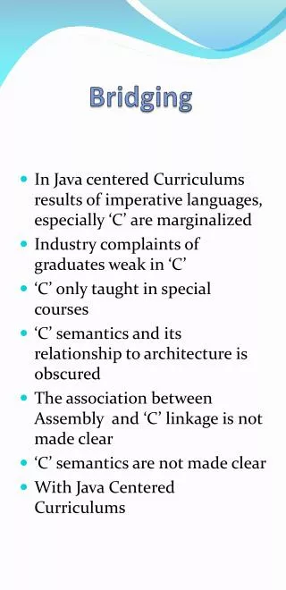
Reasons for Bridges • On a single LAN, there are limitations: • Number of stations • Size of segment • Bandwidth per segment • Bridges connect LAN segments to make “extended” LANs • LANs, LAN Segments, Extended LANs Digital Switching
Example: Bridging Benefits Consider a LAN segment with average traffic R pkts/s Divide it into two segments and connect with a Bridge Average traffic on each segment is R/2 pkts/s Bridge R/2 pkts/s R/2 pkts/s Stations Stations Digital Switching
Example: Bridging Benefits • On average: • Each segment generates a traffic of R/2 pkts/s • Half of the traffic is for “local” stations • Half of the traffic is for “other” segment • Traffic on each segment is R/2+(1/2) R/2 • Average traffic on each segment is 3R/4 • This traffic must not exceed the capacity of the segment Digital Switching
Example: Bridging Benefits • Therefore 3R/4 < C • C is the capacity of the physical link • R < 4C/3 • Effective R exceeds the capacity i.e. Rmax < 4C/3 • rate on any segment must not exceed the capacity • What was the maximum rate allowed when the LAN was not segmented? • (Rmax < C) • Does the maximum effective R (i.e., Rmax) increase when three segments are used? • Depends how the segments are connected! Digital Switching
Can we use a router instead? • The answer is “It depends” • Inter-segment traffic may be handled by routers if all stations understand layer 3 • Older machines did not understand layer 3, but new ones do • Does this mean that with newer stations, we did not need bridges? • Not really! Bridges handle all layer 3 protocols while early routers usually handled a single layer 3 protocol • Don’t multiprotocol routers do address this issue? And what about convergence to IP? Does that not eliminate the need for multiprotocol routers • An IP router can replace a bridge then, right? Digital Switching
Do we still need a Bridge? • What if stations want to move on the “extended” LAN without reconfiguring their IP addresses? • Bridges can help! • Bridges have high performance • Bridges are simple (less expensive) Digital Switching
Transparent Bridging … stations Bridge For stations, the two topologies are the same transparent bridging Digital Switching
Transparent Bridge Functions • Promiscuous Listening • Every packet passed up to software • Store and Forward • Based on a forwarding database • Filtering • Also based on forwarding database Digital Switching
Can a Bridge act smart? • For the two segment-one bridge topology for which the maximum rate was 4/3 of the link capacity, was Bridge doing something smart? • Yes, the Bridge forwarded the traffic smartly • Manual entry of station addresses? • Stations use addresses from a range? • Station addresses are assigned such that a portion indicates the LAN number? • Bridges can also “learn” on their own!!! Digital Switching
Forwarding Database (FDB):Creation and Maintenance • The bridge promiscuously listens to every packet/frame received on each port • For each received frame, address in the source field is stored together with the port on which the frame is received. The FDB is created in Station Cache. • Each entry in the FDB is deleted if no traffic is received from that source address for a given period of time (Aging time). Why? Digital Switching
Forwarding Frames • For each received frame, the bridge looks at the destination address: • If the address is multicast or broadcast (all 1’s) then the frame is forwarded to all the interfaces (ports) except for the one on which it is received • For unicast addresses: • If the address is not found in FDB, the frame is forwarded to all the ports except for the one on which it is received • If the address is found in FDB, the frame is forwarded to the port in FDB entry. If the FDB entry has same port on which the frame is received, frame is dropped (filtered) Digital Switching
Example 1: Learning and Forwarding • Transmission order • A D • Ports 2, 3 • D A • Port 1 • Q A • Filtered • Z C • Ports 1, 3 Port 1 Port 3 B Port 2 A Q D M Z C Digital Switching
Example 2: Two Bridges Port 1 Port 2 Port 1 Port 2 B1 B2 A Q D M K T What are the Station Caches after “complete” learning? Digital Switching
Topologies with Loops • Problems • Frames proliferate • Learning process unstable • Multicast traffic loops forever A LAN 1 B1 B2 B3 LAN 2 Digital Switching
Topologies with Loops • Solutions • Require that the topologies be loop-free through careful deployment of segments and bridges • Design Bridges to detect loops and complain and, perhaps, stop working • Not a good idea because loops provide redundancy • Design into the bridges an algorithm that prunes the topology into a loop-free subset (a spanning tree) • Blocking of some ports may be required • Automatically adapt to the changes in topology Digital Switching
Reconfiguration Algorithm • Configures an arbitrary topology into a spanning tree • Automatic reconfiguration in case of topology changes • The algorithm should converge for any size LAN; the stability should be achieved within a short, bounded time • Active topology should be reproducible and manageable • Transparency to end-stations is required • Must not use a lot of bandwidth Digital Switching
Spanning Tree Algorithm • A distributed Algorithm • Elects a single bridge to be the root bridge • Calculates the distance of the shortest path from each bridge to the root bridge (cost) • For each LAN segment , elects a “designated” bridge from among the bridges residing on that segment • The designated bridge for a LAN segment is the one closest to the root bridge • And… Digital Switching
Spanning Tree Algorithm • For each bridge • Selects ports to be included in spanning tree • The ports selected are: • The root port --- the port that gives the best path from this bridge to the root • The designated ports --- ports connected to a segment on which this bridge is designated • Ports included in the spanning tree are placed in the forwarding state • All other ports are placed in the blocked state Digital Switching
Forwarding frames along the spanning treeForward and Blocked States of Ports • Data traffic (from various stations) is forwarded to and from the ports selected in the spanning tree • Incoming data traffic is always discarded (this is different from filtering frames. Why?) and is never forwarded on the blocked ports Digital Switching
Root Selection: Bridge ID • Each port on the Bridge has a unique LAN address just like any other LAN interface card. Bridge ID is a single bridge-wide identifier that could be: • A unique 48-bit address • Perhaps the LAN address of one of its ports • Root Bridge is the one with lowest Bridge ID B Port Address Digital Switching