
System Sequence Diagrams for Software Modeling
E N D
Presentation Transcript
System Sequence Diagram Chandan Rupakheti & Steve Chenoweth Week 5-3a
Today • Organizing Requirements • System Sequence Diagrams • Work on demos for tomorrow
Interaction Diagrams • The term interaction diagram is a generalization of two more specialized UML diagrams types (covered in CSSE 374) • Sequence Diagram • Communication Diagram • System Sequence Diagram is a specialized form of sequence diagram, which depicts interaction between various actors and the system
Modeling Behavior from a System Perspective • A Use Case Scenario is an ordered series of operations (functions) that Actors invoke on the System
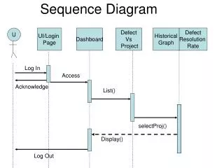
SSD Notation • Actor: An Actor is modeled using the ubiquitous stick figure symbol • Object: is represented as a rectangle which contains the name of the object underlined :Actor1 :System
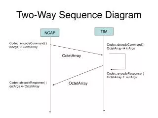
SSD Notation (continued) • Lifeline: is depicted as a vertical dotted line extending from an object that identifies the existence of the object over time • Message: modeled as horizontal arrows between activations, indicate the communications between objects messageName(argument)
External Actor Interaction Frame Return Values System as a Black Box “:” implies instance Guard Message w/Parameters SSD Notation: An Example Q1
Relating UC and SSD Note not all arrows arefunctions… some just events or information!
Why Draw an SSD? • Software systems react to three things: • External input events (a.k.a., system events) from actors • Timer events • Faults or exceptions • SSD captures system behavior: a description of what a system does, NOT how it does it • Helps transitioning towards design models from use-case model by clarifying details in use-cases Q2
How-to “Tips” on Creating SSDs • Show one scenario of a use case • Show events as intentions, not physical implementation • e.g., enterItem (not scanItem) • e.g., presentCredentials, (not enterPassword) • Start system event names with verbs • Can model collaborations between systems
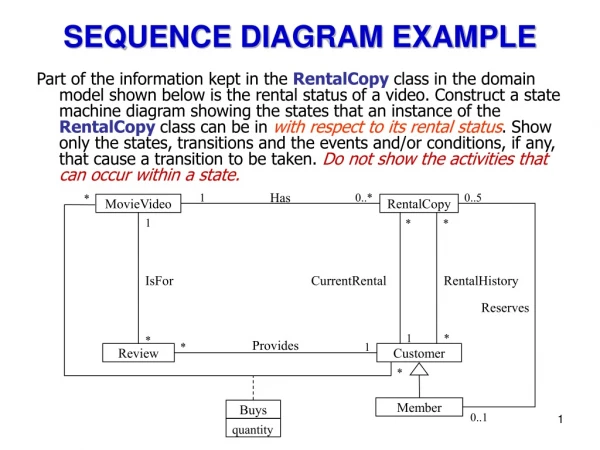
Practice Exercise – DVD Rental • UC1: Customer rents videos • Preconditions: Customer has a membership, has selected videos they want, and made system aware of their choices. • Actor: Customer (self-service/remote), or store associate (in store) • Main flow: • Actor indicates to rent first item (e.g., clicking "rent" on a networked device, or scanning it physically in a store) • System verifies immediate availability, and waits to make next option • Actor indicates they are done selecting • System shows total, prompts for payment • Actor selects method of payment, entering additional data if needed (e.g., credit card number) • System verifies the payment has gone through, schedules the goods for rental (e.g., sets up a window to click on to view the video remotely, or tells the store clerk where to find the DVD) Q3
Next … Project Work! • Work on demos for your client meeting tomorrow! • GitEnvironment • You can use Eclipse for GUI-based interface • http://www.eclipse.org/egit/