Download
1 / 11
140 likes | 289 Vues
A RTP crystal electro-optic modulator for next generation gravitational wave detector. Wan Wu, Volker Quetschke, Ira Thorpe, Guido Mueller, David Reitze, and David Tanner LIGO-G070243-00-Z. Physics Department University of Florida Gainesville, FL.

E N D
A RTP crystal electro-optic modulator for next generation gravitational wave detector Wan Wu, Volker Quetschke, Ira Thorpe, Guido Mueller, David Reitze, and David Tanner LIGO-G070243-00-Z Physics Department University of Florida Gainesville, FL Supported by NSF grant PHY-0555453, PHY-0354999 & NASA//OSS grant BEFS04-0019-0019
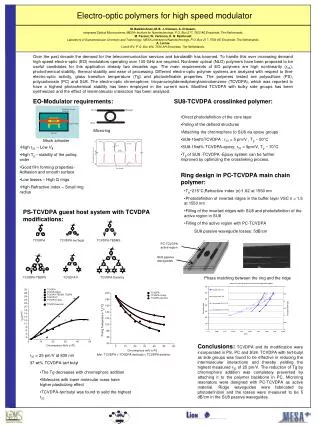
ETM Mode Cleaner ITM PRM ITM EOMs ETM BS SRM EOMs in Advanced LIGO • Part of the technical concerns for Advanced LIGO • Potential ‘thermal lensing’ headaches due to the application of 180W laser • Stringent requirement on the laser amplitude and frequency noise • Demanding requirements on EOMs: • Ultra-low optical absorption on the 1064nm laser • Negligible residual amplitude and phase noise associated with the phase • modulation
RTP crystal EOM A novel RTP ( RbTiOPO4) crystal EOM is developed for Advanced LIGO • Optical absorption coefficient< 1000 ppm/cm • (upper limit according to our measurement) • Maximum power loss of 00-mode ~ 1.4%
RFAM RFAM creates unwanted offsets in the length sensing and control signals Measured RFAM produced by RTP EOMs under high power laser heating DIW / IDC ~ 10e-5
Noise associated with EOM • EOM imposes the additional noise on the transmitted light • - Creates intensity noise of both the carrier and the sidebands • - Introduces sidebands phase noise • ( The phase fluctuation between the carrier and the sidebands causeslaser • frequency noisevia the feed back loop ) • Noise generation mechanism • - Variation of the modulation index • - Variation of the phase retardation • - Fabry-Perot cavity effect Carrier Sidebands
Measurement of the intrinsic EOM noise f 1 Nd:YAG EOM Phase meter Nd:YAG PLL f 2 • Phase lock two lasers with a frequency offset • Measure the beat signals – Carrier-Carrier(C-C), Carrier-Sidebands (C-S)
Noise in the beat notes • Noise in two beat signals (C-C, C-S) in common mode - Beam jitter between two laser beams - Laser intensity noise • Noise in two beat signalsin differential mode (amplitude & phase noise) - produced by the EOM Amplitude Common-mode noise rejection analysis Phase
Future improvement Modulation index Phase retardation Temperature stabilization is needed Use wedge crystal to eliminate the cavity effect
Our ultimate goal • Solving the noise problems associated with EOMs is a challenging • task ! • Current estimation of the requirement on the amplitude and the phase noise: • - Laser intensity noise ~ • - Sideband phase noise ~ at 100 Hz • Based on the calculation in ( K. Somiya, Y. Chen, S. Kawamura, and N. Mio, • PRD, 2006 )