Introduction to Hypersonic Propulsion Systems
Dr. Andrew Ketsdever Assistant Professor Department of Mechanical and Aerospace Engineering University of Colorado at Colorado Springs aketsdever@eas.uccs.edu http:// eas.uccs.edu/aketsdever. Introduction to Hypersonic Propulsion Systems. Technology Requirements. Propulsion System Factors.


Introduction to Hypersonic Propulsion Systems
E N D
Presentation Transcript
Dr. Andrew Ketsdever Assistant Professor Department of Mechanical and Aerospace Engineering University of Colorado at Colorado Springs aketsdever@eas.uccs.edu http://eas.uccs.edu/aketsdever Introduction to Hypersonic Propulsion Systems
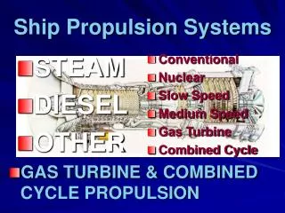
Propulsion System Factors • Efficiency • Weight • Complexity • Variability • Longevity and cost of components • Fuels (density, rheology, stowability, handling, combustion characteristics, cost) • Materials • Mission requirements (trajectory, cost, etc.)
Performance • Specific impulse • Thrust • Inert mass fraction • All three must be optimized in order to achieve desired outcome
Temperature Small Space Booster Thrust Chambers NASP Boost Glide Vehicles • Solid • Staged • Combustion Cruise Missiles Satellite Propulsion Booster Liquid Rocket Engine Nozzles Time, sec Materials
Problems • Most launch vehicles are rockets, which suffer from low specific impulse compared with air-breathing systems (5000 sec. for turbojets vs. 500 sec. for rockets) • This degrades overall performance and increases weight (a good reason to investigate hybrid systems for future launch vehicles!)
Problems • The need to carry so much fuel makes overall weight a crucial design factor • The structure of the vehicle is made as light as possible to compensate • Boosters are not strong, rigid bodies. While they are fairly strong longitudinally, they are very weak laterally • Most rockets cannot fly at significant angles of attack through the atmosphere or they would fall apart! • A rocket carrying satellites usually starts vertically, but must end in a horizontal orbit trajectory • How can you control trajectories??? • How do you keep from falling apart???
Pratt & Whitney J58 Turbo-ramjet cycle 35,000-lb thrust class, 9-stage compressor, SFC 2.17 1/hr
SUBSONIC TURBINE ENGINE HIGH ALTITUDE SUPERSONIC TURBINE ENGINE RAMJET, AIR-AUGMENTED ROCKET LOW ALTITUDE SUPERSONIC TURBINE ENGINE HYPERSONIC RAMJET Flight Regimes 200 150 ALTITUDE, KFT 100 50 0 0 1 2 3 4 5 6 7 FLIGHT MACH NUMBER
Propulsion Options Combined cycle Propulsion • “Low speed” cycle + scramjet • Rocket Based Combined Cycle (RBCC): Mach 0--25 air-breathing +rocket + scramjet + rocket • Turbine Based Combined Cycle (TBCC): Mach 0--4, 5 turbine + scramjet • Scramjet • Supersonic combustion ramjet • Hydrocarbon (Mach 3-8) • Hydrogen (Mach 3-15)
Scramjet Vehicle and Propulsion system are totally integrated No Moving Parts Necessary Mach 4 and higher Body Fuel Cowl Combustor Forebody (Compression) Nozzle Shock Wave Isolator Inlet
NASA X-34 Scramjet Program "On 16 November, 2004, NASA's unmanned Hyper-X (X-43A) aircraft reached Mach 9.6 (~7,000mph). The X-43A was boosted to an altitude of 33,223 meters (109,000 feet) by a Pegasus rocket launched from beneath a B52-B jet aircraft. The revolutionary 'scramjet' aircraft then burned its engine for around 10 seconds during its flight over the Pacific Ocean."
Turbine Based Combined Cycle (TBCC) • Accelerator Turbine (Mach 0—4.3) is combined with a duel-mode scramjet engine (Mach 4—8) • Transition from turbine power to ramjet is performed at Mach 4 Over-Under configuration Accelerator Turbines Turbine-engine inlets • Cocooning hot turbine engines will be a technical challenge • Tail rockets would likely be added if vehicle is the first stage of launch system
Rocket Based Combined Cycle (RBCC) Rocket-Based Combined Cycle promises a propulsion system that can achieve good performance from M = 0--25 Body Strut & Rockets Cowl Combustor Forebody (Compression) Nozzle Shock Wave Inlet & Door Isolator Vehicle and Propulsion system are totally integrated
RBCC Modes of Operation Air-Augmented Ejector Mode Mach = 0—3 AIR Ramjet Mode M = 3—6 AIR M <1 GREEN ARROWS: FUEL INJECTION AIR M >1 Scramjet Mode M = 6—10 Inlet Closed Rocket Mode M > 10 Each mode is sub-optimized in its operating range
3 2 Detonation wave moves Detonation is initiated through fuel-air mixture 4 Resulting high pressure gas 1 fills detonation chamber Fuel is mixed with air 5 Detonation wave exits engine Air drawn in by reduced pressure Pulsed Detonation Engines • Pulse Detonation Engine • Operating Concept Typical: 40 cycles/sec