Download
1 / 14
140 likes | 370 Vues
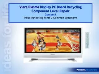
Viera Plasma Display PC Board Recycling Component Level Repair. Curriculum Content. Course 1 PCI PCB Recycling Program/Process Model line-up/PC board functionality Course 2 PCB Recycling Component Level Repair Techniques Course 3 Understanding How System Shut Down Operates Course 4

E N D
Viera PlasmaDisplay PC Board Recycling Component Level Repair
Curriculum Content Course 1 • PCI PCB Recycling Program/Process • Model line-up/PC board functionality Course 2 • PCB Recycling Component Level Repair Techniques Course 3 • Understanding How System Shut Down Operates Course 4 • Troubleshooting Hints / Common Symptoms END
Procedure for Returning Returnable PC board Servicentre determines a returnable PC board is defective. Servicecentre orders replacement PC board from Panasonic National Parts • After repairing the product, servicecentre returns the following to Panasonic National Parts: • Returnable PC board/part • Completely fill out Returnable Parts Report form • Once Panasonic National Parts receives the defective sub-assembly with all the required documents, They will: • Forward a copy of Returnable Parts form to NWCS then payment is issued to the servicentre. • Note: for O/W: NP Issues dud credit payment to servicentre for returning the defective sub-assembly.
Returnable Parts Return Form: • Must be completely filled • out and sent together with • the defective PC board. • If a board is being returned that is unused please clearly mark the form as unused.
2005/2006 PDP Line-up 2006 2005 TH-58PX600 HD Step Up Model TH-50PX600 TH-50PX500 TH-42PX600 TH-42PX500 TH-58PX60 TH-50PX50 TH-50PX60 HD Leader Model TH-42PX50 TH-42PX60 TH-37PX50 TH-37PX60 SD Leader Model TH-42PD60 TH-42PD50
2005 & 2006 PC Board Difference (for 50” models) 2005: 50PX500/PX50 2006: 50PX600/PX60 C1 C2 C3 C1 C2 C3 SS2 SS2 PB P P PA Fan Control SU SU Power Power D Audio Power DC - DC - Supply Supply Format Converter Converter SS Plasma AI Processor SS SC SC Sustain Sustain DG DT DG Drive Drive Scan Drive Scan Drive PA DT Digital Z D-TV Interface Signal DC - DC - D-TV Interface Audio Processor Converter DV Amp SD SD H HDMI D SS3 SS3 H AV Terminal HC AV Terminal C6 C5 C4 C6 C5 C4 G GK GS GS G GK K S K S Front Terminal Front Terminal PC Card SD Card SD Card Key SW Key SW REMOTE, LED POWER SW REMOTE, LED POWER SW PX500only Differences 1. The PB and Z board are now on the PA Board 2. Location of the PA and D board was changed 3. HDMI interface (DV) relocated. 4. HC board added(factory use)
2005: 42/37/PX500/PX50/PD50 2006: 42/37/PX600/PX60/PD60 C1 C2 SS2 PB P P PA Fan Control SU SU Power Power D Audio Power DC - DC - Supply Supply Converter 2005 & 2006 PC Board Difference (for 42 & 37” models): Format Converter SS SS Plasma AI Processor DT SC SC Sustain Sustain DG DT Drive Drive Scan Drive Scan Drive PA D-TV Interface Digital D-TV Interface Z Signal DC - DC - H Audio Processor Converter DV Amp SD SD H DG D HDMI AV Terminal SS3 AV Terminal HC C4 C3 C1 C2 G GK GS G GK GS K S K S Front Terminal Front Terminal Key SW SD Card Key SW SD Card PC Card REMOTE, LED POWER SW REMOTE, LED POWER SW PX500only PX600/60only • Differences • The PB and Z board are now on the PA Board • Location of the PA and D board was changed • HDMI interface (DV) relocated. • HC board added(factory use) • Reduce the upper C boards for single scan. • Reduce the S2 and S3 boards.
Easier connectionand parts change 2005 & 2006 PC Board Difference: Connecting behind the board Connecting on the board Lead connector → Bridge connector After After Before SU board Before
Input Source Signal Processor Panel Drive DT PX600 PX60 only General Signal Circuit Flow for 2006 Model (42V & 37”): GS SU D SC DG Panel (HD or SD) SS H SD K G GK C2 C1 HDMI PX600 PX60 only SPEAKER (L/R) PA SC: Scan Drive SU: Scan Out (Upper) SD: Scan Out (Lower) SS: Sustain Drive C1: Data Drive (Right) C2: Data Drive (Left) DT: ATSC Interface and tuner H : AV Terminal / AV Switch PC (PX600 Only) GK: Key Switch K : Remote Receiver / Power LED G : Front terminal GS: SD Card Slot (PX600/60 Only) DG: Digital Signal Processor / HDMI Interface D : Format Converter / Plasma AI Processor / Sub-Field Processor PA: Audio AMP / Speaker out
LVDS (*1) TRANSMITTER IC4036 Analog Digital GS HDMI I/F IC4026 HDMI2 SD Card DG HDMI1 DT ATSC LSI PEAKS LITE IC8240 IC8211 MAIN MICRO PROCESSOR IC1103 TUNER Included OSD General Video Signal Processing: PX600/60 series H V Y/C (for Monitor Out) R,G,B,HS,VS PC OSD VIDEO SWITCH IC2601 R,G,B :10Bit (MAIN) R,G,B :10Bit IC2601 Y,Pb,Pr (Main) Y,C / V GC5 10bit A/D IC4019 AV1 IC4037 LVDS Signal To D Board Y,C / V AV2 Y,Pb,Pr (Sub) GC3 FS IC4020 Y,Pb, Pr Comp.1 R,G,B :10Bit (Sub) Y,Pb,Pr Comp.2 Y/C Monitor Out <H Board> IC2601 : VIDEO SELECT <DG Board> IC4019 : A/D CONVERTER (10Bit) IC4020 : SIGNAL PROCESSOR (For SUB WINDOW) IC4037 : SIGNAL PROCESSOR (I/P CONV. ,RESIZE MIX … ) IC4036 : LVDS TRANSMITTER IC1103 : MAIN MICRO PROCESSOR PX600 only G Y,C / V AV3 (*1) LVDS : Low Voltage Differential Signaling
Thank You For Completing Course One Course Two PCB Recycling Component Level Repair Techniques