SEMINAR ON SURFACE MOUNT TECHNOLOGY
SEMINAR ON SURFACE MOUNT TECHNOLOGY. By- MARODE DNYANESHWAR D. B.E.(E&C). OUTLINE. Surface Mount Technology Role of SMT Benefits Surface Mount Devices Advantages Challenges. Surface Mount Technology.

SEMINAR ON SURFACE MOUNT TECHNOLOGY
E N D
Presentation Transcript
SEMINAR ON SURFACE MOUNT TECHNOLOGY By- MARODE DNYANESHWAR D. B.E.(E&C)
OUTLINE • Surface Mount Technology • Role of SMT • Benefits • Surface Mount Devices • Advantages • Challenges
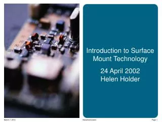
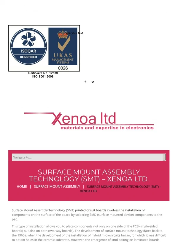
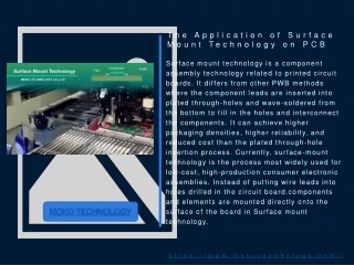
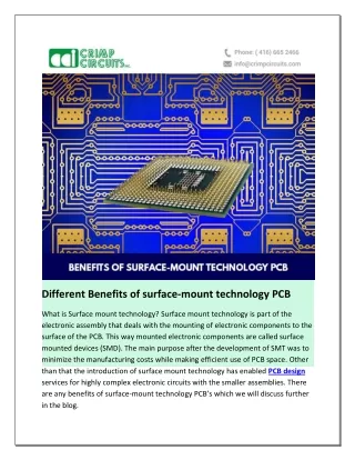
Surface Mount Technology • SMT is a Technology that uses surface mount devices, which are often leadless and require small space. • Allows high-speed component mounting and reduces PCB size. • Supports Advance consumer products ( LCD color TV, video cameras & so on). • Has the great advantage in portable stereos, CD players.
ROLE OF SMT IN ELECTRONIC WORLD • Play a predominant role to increase area efficiency & the corresponding to the system volume. • Electrical and Mechanical features are only achievable with SMT. • Small light weight portable components are mount only by using SMT. • SMT entails making reliable interconnections on the board at great speed, in the smallest possible area.
BENEFITS OF SMT • Reduction in package size. • Reduction in weight of product. • Noise Reduction. • Higher operating speed due to shorter interconnections.
COMPONENT PLACEMENT SMD’s on both sides. SMD’s on one side & discrete components on other sides. Randomly distributed on either sides.
Processes used for placement of components • Screen Printing Method. • Glue Method.
SCREEN PRINTING METHOD Paste Application on PCB by SCREEN PRINTING Pick & Place of components by HP-180 & SP-120 Visual Inspection Manually Reflow Process
GLUE METHOD • Glue Application on PCB by HS-180 • Pick & place of components by HP-180 & SP-120. • Visual Inspection Manually. • Reflow Process to cure Glue. • Wave Soldering Process.
MACHINES USED SP 120 Manufactured by Siemens It is multi headed machine Placement speed is 7200 components/ hour Easy to used Window based Software
HS 180 Manufactured by Siemens It is single headed machine Placement speed is 4200 components/hour
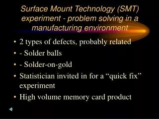
CHALLENGS Need latest Technology Requires well trained worker Complications