Download
1 / 37
940 likes | 2k Vues
Process Instrumentation and Control System Overview. CM4110 Unit Operations Lab November 2007. Outline. 100-yr. Evolution of Process Instrumentation Process Measurements, Then and Now Choosing the Right Instrument Process Instrumentation Connections to Control System

E N D
Process Instrumentation and Control System Overview CM4110 Unit Operations Lab November 2007
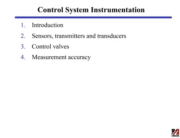
Outline • 100-yr. Evolution of Process Instrumentation • Process Measurements, Then and Now • Choosing the Right Instrument • Process Instrumentation Connections to Control System • Overview of Data Management and Control Systems • Career Opportunities in Process Control
Background Important Discoveries • 1592 – 1st thermometer • 1701 – first practical thermometer • late 1700’s – temperature is not a fluid! • 1821 – thermocouple effect • 1880 – first controller • 1885 – effect of temperature on conductivity • late 1800’s – metals have different thermal expansion effect Fisher Type 1 pump controller, 1880
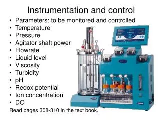
Background – Beginning of Industrial Revolution to ~ 1920’s • Temperature readings by a Thermometer or colorimetric method or Bimetallic Device • Pressure by Bourdon Tube gages • Level by Sight Glass • dP by Manometer • Pen Chart Recorders
Background – Several Surviving Technologies Optical Pyrometer – Color used to measure high Temp Bi-metallic Temperature measurement – similar to Bourdon tube Bourdon tube for Pressure or Temp measurement
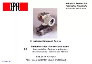
Background – Need to Transmit Signals to Directly Control the Process 1930’s • Transmitters used to convert sensing device signal to pneumatic signal • Feedback controllers invented – PID • Improvements in valve design to better control process • Valves fitted with pneumatic actuators Foxboro Flow Controller w/ 24-hr. Chart Recorder
Background – Further Improvements in Signal Transmission and Control Early 1960’s • Most process signals can be converted to low-level electric by transmitter • 4-20 mA current loop becomes standard for analog devices • Early computers used to control process • More control valve design improvements
Background – Instrumentation Developments in the Last 20 Years • Recognized weaknesses of 4-20 mA current loop • needs continuous re-zero and re-range • transmits PV in a scaled format only • 1988 - Digital Instrumentation with Self-calibration, Diagnostics, Messaging capability • 1998 - Networked instrumentation - Bus systems for Process Instruments • Current - Wireless Transmitters and Self-Organizing Networks
Background – Control System Developments in the Last 20 Years • Early 1980’s - DCS introduced, control intelligence is distributed throughout plant • Late 1990’s - Control Systems built on commodity hardware platforms and OS • 2000’s - Improvements in Graphical Interface, Data Acquisition, Advanced Control, Process Management
Choosing the Right Instrument • Instruments are the eyes and ears of the plant • Many choices available • Instruments and valves need to be selected, sized and installed properly
Options for Local Temperature Measurement • Glass stem Thermometer • low cost, long life • local readout, difficult to read, no transmitter • -200 to 600ºF, 0.1ºF accuracy • Bi-metallic Thermometer • low cost • -80 to 800ºF, 1ºF accuracy
Options for Local Temperature Measurement/ Control • Fluid-filled Thermal Elements • low cost, long life • -300 to 1000ºF, ±½% of full scale accuracy • low accuracy, great for some applications where tight control is not req’d • self-contained, self-powered control (can use fluid expansion to proportionally open control valve) • dial read-out for indication, can be remotely located
Options for Local or Remote Temperature Measurement • Thermocouples • low cost sensor • -440 to 5000ºF, typically 1 to 2ºF accuracy • wide temperature range for various types • rugged, but degrades over time • many modern transmitters can handle T/C or RTD
Options for Local or Remote Temperature Measurement • RTD’s • -300 to 1150ºF, typically 0.1ºF accuracy • more fragile, expensive than T/C • better accuracy and reliability than T/C • very stable over time • wide temperature range
Options for Flow Measurement • Differential Pressure – Orifice Meter • well-characterized and predictable • causes permanent pressure (energy) loss in piping system, typically 8’ W.C. loss (3 to 4 psi loss) • 5:1 rangeability • requires straight run of 20 pipe diameters upstream, 5 downstream • suitable for liquid, gas, and steam • accuracy is 1 to 2% of upper range
Options for Flow Measurement • Turbine Flow Meter • accuracy is ±0.25% of rate • good for clean liquids, gases • 5 to 10 pipe diameters upstream/downstream • 10:1 turndown • 3 to 5 psig pressure drop
Options for Flow Measurement • Magnetic Flow Meter (Mag Meter) • 0.4 to 40 ft/s, bidirectional • accurate to ±0.5% of rate • fluid must meet minimum electrical conductivity • head losses are insignificant • good for liquids and slurries • upstream/downstream piping does not effect reading • linear over a 10:1 turndown
Options for Flow Measurement • Vortex Flow Meter • suitable for liquids, steam, and gases • must meet min. velocity spec • 0.5 to 20 ft/sec range for liquid • 5 to 250 ft/sec for gases • non-clogging design • not suitable if cavitation is a problem • accuracy is ±½% of rate • up to 5 psig head loss • linear over flow ranges of 20:1
Options for Flow Measurement • Coriolis Effect Mass Flow Meter • used for steam, liquids, gases • measure mass flow, density, temperature, volumetric flow • expensive, but 0.2% of rate accuracy • very stable over time • 100:1 turndown • negligible to up to 15 psig head loss
Options for Level Measurement • Non-Contacting – Radar Level • suitable for liquids and solids • foaming, turbulence, vessel walls and internals can effect signal if not installed correctly • can use “stilling leg” if turbulence is extreme • typically ±0.1 inch accuracy
Options for Level Measurement • Contacting – dP Level • suitable for liquids only • foaming and turbulence will effect signal • can use “stilling leg” if turbulence is extreme • typically ±0.05% range accuracy • 100:1 turndown • uses same dP transmitter as in dP flow measurement
Pressure Measurement • Pressure Transmitters • available in gage pressure, absolute pressure and differential pressure • typically ±0.075% range accuracy • 50:1 turndown • same transmitter and sensor body as in dP flow measurement and dP level
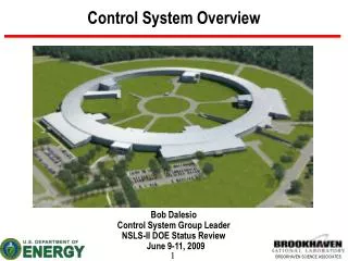
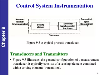
Instrumentation Ties Process to Control System • Wiring systems connect instrumentation to the control system • Input devices used to “see” what’s going on in the process • Control Systems make decisions based on process inputs, operator inputs, and control software • Output devices control the process
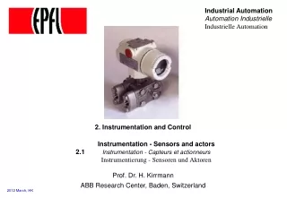
Wiring Systems Connect Transmitters to DCS – at the Instrument End: Wiring to field junction cabinet Level transmitter RTD or T/C head Wiring from transmitter to temp measuring element Temperature transmitter
8 pr. Cables to controller cabinet Wiring Systems Connect Transmitters to DCS – at the Marshalling Cabinet: Single pairs from field devices 8-pr. cables run from Field Junction Box (Marshalling Cabinet) to Distributed Control System
Wiring Systems Connect Transmitters to DCS – at the Controller Cabinet: DeltaV MD controller I/O cards Power-limiting Zener barriers 8 pr. cables from field junction cabinet 2nd I/O chassis w/4-20 mA Output cards
Wiring Systems Connect DCS to Transducers – at the Marshalling Cabinet: 8-pr. cable from field junction cabinet Current to pneumatic transducers Wire prs. to transducers Air lines to control valves
Installed Field DevicesRegulatory Control Valve Air line from I/P transducer Actuator w/ positioner Control valve Block valves Bypass valve
Output Signals from Control Systemto Control Solenoids 8-pr. cable from field termination cabinet Solenoids for 2-position air-actuated ball valves Air lines to ball valves Wire prs. to solenoids
Installed Field DevicesBall Valve w/ Actuator Air line from solenoid Ball valve body Actuator Process line
DeltaV & Foundation Fieldbus (4) mass flows, (4) densities, (4) RTD temps (3) 8-multiplexed RTD temps (2) temp-only transmitters
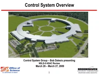
MD Controller PSCC_DeltaV Redundant Hub ProPlus Station Operator WorkStations DeltaV System – How it works: • Control Network is Windows XP Workgroup – PSCC_DeltaV, uses Windows Networking and TCP/IP protocol • Control system configuration and operations graphics building are done thru ProPlus and/or Professional Workstations • ProPlus station stores configuration and archives data, displays information • Operator stations archive data, display information
DeltaV & MD Controller – What it does… • PID control, discrete logic control, signal conversions, alarming, Fuzzy control, etc. are continuously executed by the MD controller • Field instruments and final control elements are wired individually to the I/O cards in the MD controller • Networked instrumentation data transfer – Foundation Fieldbus, ASi bus, DeviceNet, etc.
Career Opportunities in Process Control Process Control Engineer “must haves:” • Understanding of the process and of Chemical Engineering Fundamentals • Understanding of process dynamics and process response • Understanding of applications of feedback control and opportunities for advanced control • Be willing and able to work effectively with process operators
Career Opportunities Responsibilities of Process Control Engineers • Tuning controllers for performance and reliability • Selecting proper control scheme • Process troubleshooting • Automating routine processes and procedures • Implementing process optimization and quality improvement projects • Documentation and training
Career Opportunities Advantages of a Career in Process Control • Become a valuable “go-to” person in the plant • Good visibility thru implementation of high-value, short ROI projects • High demand across the industry • Good pay • Opportunities for consulting abound
References Miller, Richard W., Flow Measurement Engineering Handbook, 3rd Ed., McGraw-Hill, New York, 1996. Riggs, James B., Chemical Process Control, 2nd Ed., Ferret Publishing, Lubbock, TX, 2001. Taylor Instrument Division, The Measurement of Process Variables, no date. www.emersonprocess.com/rosemount/, Rosemount, Inc., Oct. 2006. www.emersonprocess.com/micromotion/, Micro Motion, Inc., Oct. 2006. www.ametekusg.com/, Ametek, Inc. Oct. 2006.