Static Analysis: Truss Element Equations
Static Analysis: Truss Element Equations. Objectives. Section II – Static Analysis Module 3 – Truss Element Equations Page 2. The objective of this module is to show how the equations developed in Modules 1 and 2 convert to matrix equations for a typical element.

Static Analysis: Truss Element Equations
E N D
Presentation Transcript
Static Analysis: Truss Element Equations
Objectives Section II – Static Analysis Module 3 – TrussElement Equations Page 2 The objective of this module is to show how the equations developed in Modules 1 and 2 convert to matrix equations for a typical element. • Notation familiar with upper division undergraduate students is used instead of the more compact indicial notation introduced at the graduate level. • The various differentials, variations, and time derivatives of Green’s strain used in the Lagrangian rate of virtual work are developed. • A one-dimensional truss element is used to demonstrate the process • It contains most of the features of multi-dimensional elements, • The integrations can be carried out manually.
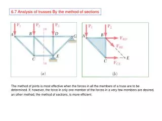
Configurations Section II – Static Analysis Module 3 – Truss Element Equations Page 3 Q* • An arbitrary line element is defined by points P & Q in the reference configuration. • The same points are defined by P* and Q* in the current configuration. Body in Current Configuration P* y,y* Body in Reference Configuration Q P x,x* • f, g & h are functions that relate the coordinates of a point in the current configuration to the coordinates in reference configuration. z,z*
Deformation Gradient Section II – Static Analysis Module 3 – Truss Element Equations Page 4 • A differential change in the reference configuration and current configuration coordinates are related through the deformation gradient. Differential Changes Matrix Form • The Deformation Gradient is defined by the array [F]. • It is the Jacobian of the transformation between the current and reference configurations.
Deformation Gradient Components Section II – Static Analysis Module 3 – Truss Element Equations Page 5 • The displacements ux, uy, and uz in the x, y and z directions can be used to determine the mapping functions f, g and h. Current Configuration y Using these functions, the components of the deformation gradient become Reference Configuration x z
Green’s Strain Section II – Static Analysis Module 3 – Truss Element Equations Page 6 • Green’s strain is defined by the equation Small strain definition • Green’s strain uses the length squared of a differential line element instead of the differential length. • For small displacements and rotations, Green’s strain and the small strain give similar results.
Green’s Strain and Deformation Gradient Section II – Static Analysis Module 3 – TrussElement Equations Page 7 • The Deformation Gradient is the fundamental building block needed to find the components of Green’s strain Reference Configuration Current Configuration Deformation Gradient
Components of Green’s Strain Section II – Static Analysis Module 3 – Truss Element Equations Page 8 • The combination of equations on the previous slide gives the equation Green’s Strain where Components of Green’s Strain This equation is used extensively in subsequent slides.
Green’s Strain – Displacement Equations Section II – Static Analysis Module 3 – TrussElement Equations Page 9 • The Deformation Gradient can be used to find the equations for the component of Green’s strain commonly found in textbooks. Carrying out the matrix operations yields
Truss Element Geometry Section II – Static Analysis Module 3 – Truss Element Equations Page 10 • Element matrices are derived using the element coordinate system. They can be transformed to the global coordinate system at the end. Node j Current Configuration Element Coordinate System Y X,Y, Z Global Coordinate System x,y,z Element Coordinate System x Node i y Node j Reference Configuration Node i X z Global Coordinate System Z
Notation Section II – Static Analysis Module 3 – Truss Element Equations Page 11 • Quantities that have an over score are associated with a node point (i.e. node i or node j). • In the array, is equal to the x displacement measured at node i.
Truss Interpolation Functions Section II – Static Analysis Module 3 – Truss Element Equations Page 12 • The displacement or virtual velocity components at any point along the length of the element can be found using interpolation functions. where Note that at x = L, N1 = 0 and N2 = 1, at x = 0, N1 = 1 and N2 = 0.
Tangent Stiffness Matrix Equations Section II – Static Analysis Module 3 – Truss Element Equations Page 13 • The Newton-Raphson equations developed in Module 2 are • The left hand side of this equation can be written as where 2nd Integral 1st Integral 3rd Integral 4th Integral • The first two integrals are evaluated in subsequent slides. The third and fourth integrals are not as important for common problems and are not evaluated.
1st Integral: Stress Increment Section II – Static Analysis Module 3 – Truss Element Equations Page 14 • The first integral that contributes to the tangent stiffness matrix is • The differential of the matrix containing the components of the 2nd Piola stress tensor can be related to the differential of Green’s strain via material constitutive equations. • For a truss element made from a linear elastic material this equation becomes • Where Y is Young’s Modulus.
1st Integral: Differential of Green’s Strain Section II – Static Analysis Module 3 – Truss Element Equations Page 15 • The first integral also requires equations for the differential of the virtual rate of Green’s strain. • All six components are given, but only dExx is needed for the truss element.
1st Integral: Differential of Green’s Strain Section II – Static Analysis Module 3 – Truss Element Equations Page 16 • The truss element interpolation functions can be used to evaluate dExx for the truss element.
1st Integral: Differential of Green’s Strain Section II – Static Analysis Module 3 – Truss Element Equations Page 17 • Combining the equations from the previous slide and writing them in matrix notation yields • The array BL contains the linear terms and array BNL contains the displacement dependent non-linear terms. 1x6 1x1 6x1 where
1stIntegral: Virtual Rate of Green’s Strain Section II – Static Analysis Module 3 – Truss Element Equations Page 18 • The first integral also requires equations for the virtual rate of Green’s strain. • All six components are given, but only is needed for the truss element.
1stIntegral: Virtual Rate of Green’s Strain Section II – Static Analysis Module 3 – Truss Element Equations Page 19 • In a manner similar to that used for the differential of Green’s strain, these equations can be written as 1x6 1x1 6x1 where
1st Integral: Final Form Section II – Static Analysis Module 3 – Truss Element Equations Page 20 • Collecting terms from previous slides and carrying out the integration yields the equation for the 1st integral or where 1x6 6x6 Relates element strain increments or rates to the node point displacement increments or rates. Contribution to Tangent Stiffness Matrix
1st Integral: Material Stiffness Matrix Section II – Static Analysis • Module 3 – Truss Element Equations Page 21 • This 6x6 matrix is a function of Young’s modulus and is thus dependent on the material. It is also a function of the length and cross sectional area. • The matrix [B] contains two contributions. [BL] is linear and leads to the linear stiffness matrix, [KL] . [BNL] is a function of the displacements and changes as the truss element deforms. This gives rise to a non-linear stiffness contribution. This contribution to the tangent stiffness matrix is denoted as [K(u)]. Linear Stiffness Matrix
2nd Integral: Differential of Virtual Rate of Green’s Strain Section II – Static Analysis • Module 3 – Truss Element Equations Page 22 • The second integral is • Carrying out the matrix multiplications yields • This is the only component needed for a truss element.
2nd Integral: Manipulations Section II – Static Analysis Module 3 – Truss Element Equations Page 23 • The integrand for a truss element is • The integrand can be written in matrix form as
2nd Integral: Interpolation Functions Section II – Static Analysis • Module 3 – Truss Element Equations Page 24 • The integrand becomes • Using the interpolation functions the partial derivatives can be written in terms of node point values • and the integral becomes where
2nd Integral: Initial Stress Stiffness Matrix Section II – Static Analysis Module 3 – Truss Element Equations Page 25 Truss Element Initial Stress Stiffness Matrix General Form for other Element Types
Restoring Force Section II – Static Analysis Module 3 – Truss Element Equations Page 26 • The restoring force comes from the internal rate of virtual work term • The virtual rate of Green’s strain for the truss element is given on previous slides as • The truss element internal rate of virtual work becomes
Restoring Force Section II – Static Analysis Module 3 – Truss Element Equations Page 27 • Since Txx and the components of BL and BNL are constant over the volume of the element, the previous equation reduces to or where This is a 6 x 1 array that has units of force.
Module Summary Section II – Static Analysis Module 3 – Truss Element Equations Page 28 • This module has shown how to go from the incremental form of the rate of virtual work to the matrix equations for an element. • The deformation gradient and its variations and derivatives are key ingredients to this process. • A truss element was used because the element level integrations can be carried out by hand. • Matrix notation is used in-lieu of the more common indicial notation.