Emissions
Emissions. Air is made up of :. 21%O2 78%N 1% other gasses (mostly argon). Fuel is primarily made up of :. Hydrocarbons (HC). Perfect combustion. HC, O2, N2 in Heat, H2O, CO2 and N2 out. Imperfect combustion. Adds HC, CO, NOx and O2 to exhaust. Stoichiometric.


Emissions
E N D
Presentation Transcript
Air is made up of : • 21%O2 • 78%N • 1% other gasses (mostly argon)
Fuel is primarily made up of : • Hydrocarbons (HC)
Perfect combustion • HC, O2, N2 in • Heat, H2O, CO2 and N2 out
Imperfect combustion • Adds HC, CO, NOx and O2 to exhaust
Stoichiometric • Much of our emissions are related directly to A/F mixtures • Theoretical best A/F ratio for emissions, economy, performance is 14.7:1 • 14.7 pounds of air to 1 pound of fuel
Think about it • Gasoline weighs 6 pounds per gallon • Air weighs 1 pound per 100 gallons • At 15:1 it takes 9000 gallons of air to burn 1 gallon of fuel • 9000 Gallons of air is equal to a single car garage
HC - Hydrocarbons • Unburned fuel • Currently measured in parts per million (ppm)
Common causes of high HC • Missfiring will cause HCs • Ignition • Mechanical • Lean • A/f ratios off either way • Timing too advanced • Cools exhaust and cylinder walls
Not so common causes of HC • Quench areas in combustion chamber • Carbon • Poor combustion chamber design • Cam profiles too aggressive
CO - Carbon monoxide • Currently measured in % • EXTREMELY deadly gas!!! • Partially burned fuel • Too much fuel or too little O2 • Combustion process ran out of air • CO directly related to a/f ratios
Causes of high CO • Any thing that will cause a rich fuel mixture • Sensor malfunction • Carburetor or injector failures • Diluted oil • Hard to use as an A/F guide over 15:1 due to flattening out of curve • Must use O2 above stoichiometric
O2 - Oxygen • Currently measured in % • Unused air in exhaust • O2 directly related to A/F • Can also come from dilution • Air pump, exhaust leaks • Missfires will raise O2 • If O2 is > 5% and vehicle running OK then it must be from dilution
CO2 - Carbon dioxide • Currently measured in % • Byproduct of complete combustion • Peak indicates good A/F • Any problems pull CO2 away from peak • Used by Washington State to determine exhaust system integrity
NOx - Oxides of nitrogen • Created when peak combustion temps. exceed 2500F
Causes of high NOx • Advanced timing • Inoperative EGR • Carbon build up • Anything that overheats combustion chamber
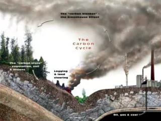
Smog, what is it? • Ground level ozone - O3 • Three ingredients; HC, NOx and sunlight • CO is a pollutant all by itself
State emissions testing • Attainment areas vs. non-attainment areas • Ozone and/or CO • Centralized vs. non-centralized testing
ASM test • Loaded test with constant load with a CVS • Idle test • With or without an evaporative emissions test • Test all three gasses
Washington State test • Variation of a ASM test • Loaded cruise test except special vehicles • Idle test • No NOx measuring in effect yet
IM240 test • Varying load test with a constant volume sampler • Idle test • Evaporative emissions test • Testing all three gases • Visual inspection
Remote sensing devices • Like photo radar • Used in California / Colorado
Purpose of PCV • Control of blowbye gasses (HC) • Reducing moisture and acids extending oil life
PCV history • Road draft tube was responsible for 20-25% of vehicles emissions • Completely sealed systems on all domestics since 1968
Components of PCV • Breather to filter incoming air • PCV valve • Calibrated vacuum leak to intake manifold • Controls flow rates based on strength of vacuum • Eliminates backfiring path to crankcase • Bleed orifice type / dual bleed type
PCV system problems • Can flow up to 20% of the total a/f mixture at idle • Plugged system could cause high CO at idle • Stuck open valve could cause lean or high idle speed
PCV system diagnosis / testing • Valve should snap back at idle • Rattle test • Cheap valves pass both tests but could flow wrong • Inspect breathers for plugging • Oil dilution • 1% Change = too much dilution or blowbye
Evap system purpose • To control HC during fuel evaporation
Evap system components • Gas cap • Important seal of system • Easily over looked • Allows air in but pressure out only if >1 psi • Vapor liquid separator
Evap system components • Canister • Stores evaporating vapors • Approx. 1.5 Lbs. Activated charcoal • Can hold twice it’s own weight in fuel • Chrysler used the crankcase in 1971 • Vapor line(s) from tank(s) • Carb bowl venting • Electronic solenoids • Switching with purge valve
Evap system operation (purging) • Uses stored fuel vapors in canister • Variable type-hose to air cleaner snorkel • Constant purge type-vacuum to manifold • Uses TVS and orifice
Evap system operation (purging) • Demand system • None at idle • Uses ported vacuum as control • Manifold vacuum does purging • Needs TVS • Computer controls • OBDII diagnostics
Evap system problems • Failed purge valves / diaphragms rupturing • Plugged filters • Failing TVS can cause cold flooding • Loaded canister due to over full tanks • Charcoal in carb. bowl indicates defective canister
EFE system purpose • Helps a/f mixture vaporize on cold engine • Provide good cold driveability (cold air too dense and leans out mixture) • Improve cold emissions
EFE system purpose • Warms intake to prevent condensation of fuel • Prevents icing in carbs (temps can drop 66f when fuel vaporizes)
Four types of EFE • 1. T.A.C. (thermostatic air cleaner) • 2. EFE grid • 3. Coolant heated intakes and throttle bodies • 4. Heat riser valve
T.A.C. components • Mode door • Cold air position for warm eng. • Warm air position for cold eng. • Uses manifold vacuum and vacuum motor to move mode door • Heat stove and pipe • Primary failure of emission tests
T.A.C. components • Sensor • Bleeds off vacuum at 100 - 120f • Must bleed off vacuum - can not trap it • Wax bulb type • Manual movement (older asians)
T.A.C. problems • Stuck in hot air position will cause ping / NOx • Often caused by a plugged bleed off hole • Any missing piece can cause cold driveability problems • Cracked manifold sucks exhaust into air cleaner
EFE grid components • Electrical heater • Usually only, on carburetors and only on primary bore(s) • Commonly ceramic
EFE grid operation • Heats and mixes a/f mixture • Controlled by switches or relay • Usually powered up cold only
EFE grid problems • Grids melt • Switches stick on • Heater element opens
Coolant passages • Primarily icing controls • Also helps warm intakes
Heat riser valve purpose • Directs exhaust to underside of intake manifold • Prevents condensation • Improves vaporization • Not necessary on PFI engines
Heat riser valve components • Vacuum with rod • Uses TVS • Bimetal spring • On V engines valve will plug off one side of exhaust when cold