Download
1 / 11
110 likes | 260 Vues
Optimal Recovery Schemes for Fault Tolerant Distributed Real-Time Systems. Lars Lundberg and Charlie Svahnberg Department of Computer Science, University of Karlskrona/Ronneby, Sweden. Broken Computer. I/O. Active Computer. Active Computer. I/O. I/O. Active Computer. Standby

E N D
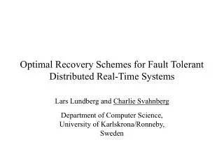
Optimal Recovery Schemes for Fault Tolerant Distributed Real-Time Systems Lars Lundberg and Charlie Svahnberg Department of Computer Science, University of Karlskrona/Ronneby, Sweden
Broken Computer I/O Active Computer Active Computer I/O I/O Active Computer Standby Computer Standby Computer Fault Tolerance (fail over)
Computer 0 Recovery order for process 0 Computer 1 Computer 2 Computer 3 Recovery order for process 0 Computer 1 Computer 2 Computer 3 Recovery order for process 0 Computer 1 Computer 2 Computer 3 I/O to process 0 Computer 0 Computer 0 I/O to process 0 I/O to process 0 Process 0 Computer 1 Recovery order for process 1 Computer 2 Computer 3 Computer 0 Recovery order for process 1 Computer 2 Computer 3 Computer 0 Recovery order for process 1 Computer 2 Computer 3 Computer 0 I/O to process 1 Computer 1 Computer 1 Process 0 I/O to process 1 I/O to process 1 Process 1 Computer 2 Process 2 Process 3 Process 2 Process 1 Process 2 Process 3 Process 3 Recovery order for process 2 Computer 3 Computer 0 Computer 1 Recovery order for process 2 Computer 3 Computer 0 Computer 1 Recovery order for process 2 Computer 3 Computer 0 Computer 1 I/O to process 2 Computer 2 Computer 2 I/O to process 2 I/O to process 2 Process 0 Computer 3 Process 1 Recovery order for process 3 Computer 0 Computer 1 Computer 2 Recovery order for process 3 Computer 0 Computer 1 Computer 2 Recovery order for process 3 Computer 0 Computer 1 Computer 2 I/O to process 3 Computer 3 Computer 3 I/O to process 3 I/O to process 3 Fault Tolerance continued Instead of having one (or a number of) standby computers just hanging around, we would like to distribute the work to all the computers in the cluster. To start with we assume that there is one process on each computer. The recovery order for each each process is determined by a recovery order list. The set of all recovery order lists is referred to as recovery scheme.
Computer 0 Computer 0 Computer 0 Computer 2 Computer 1 Computer 3 Computer 2 Computer 3 Computer 0 Recovery order Computer 1 Computer 3 Computer 2 Recovery order Computer 1 Computer 3 Computer 2 Recovery order Computer 2 Computer 0 Computer 3 Recovery order Computer 3 Computer 1 Computer 0 Recovery order Computer 0 Computer 2 Computer 1 Recovery order Computer 0 Computer 2 Computer 1 Recovery order Computer 3 Computer 1 Computer 0 Recovery order Computer 1 Computer 3 Computer 2 I/O to process 0 I/O to process 0 I/O to process 3 I/O to process 2 I/O to process 3 I/O to process 1 I/O to process 2 I/O to process 0 Process 0 Computer 1 Computer 1 Recovery order Computer 2 Computer 0 Computer 1 Recovery order Computer 2 Computer 0 Computer 3 Process 2 Process 3 Process 1 Process 2 Process 3 Process 2 Process 3 I/O to process 1 I/O to process 1 Process 1 Process 0 Computer 2 Recovery order Computer 3 Computer 1 Computer 0 I/O to process 2 Process 1 Computer 3 Recovery order Computer 0 Computer 2 Computer 1 I/O to process 3 Process 0 Changing the Recovery Order Lists The problem with the simple and intuitive recovery order lists on the previous slide was that we could end up with three processes on the most heavily loaded computer when two out of four computers break down. If we generalize the schemes to n computers we could end up with x+1 processes on the most heavily loaded computer when x computers are down. However, by using a different set of recover order lists we can make sure that there will never be more than two processes on each computer when two out of four computers break down.
Recovery list Computer 1 Computer 2 Computer 3 Recovery list Computer 2 Computer 3 Computer 0 Recovery list Computer 3 Computer 0 Computer 1 Recovery list Computer 0 Computer 1 Computer 2 Telecom switch Recovery list Computer 1 Computer 2 Computer 3 Recovery list Computer 2 Computer 3 Computer 0 Recovery list Computer 3 Computer 0 Computer 1 Recovery list Computer 0 Computer 1 Computer 2 Comp. 0 Telecom switch Comp. 0 Comp. 1 Cluster with four computers Telecom switch Comp. 1 Telecom switch Telecom switch Comp. 2 Telecom switch Comp. 2 Comp. 3 Telecom switch Comp. 3 Telecom switch Why do we consider static recovery lists, i.e. why not use dynamic load balancing - The real-time behavior of dynamic schemes is often unpredictable - A number of commercial cluster system do not support dynamic load balancing, e.g. Sun cluster - In some cases the load to the cluster nodes is generated by external systems, e.g. telecommunication exchange stations, and in that case the communication has to be redirected. This is often done by having alternative addresses (primary address, secondary address etc.) in the external systems. These addresses have to be decided statically.
Notations for a cluster with n computers • L(n,x,{c0,…,cx-1},RS) (n > x) denotes the load on the most heavily loaded computer when computers c0,…,cx-1 are down and when using a recovery scheme RS • L(n,x,RS) = maxL(n,x,{c0,…,cx-1},RS) for all vectors {c0,…,cx-1} • V(L(n,RS))= {L(n,1,RS),…,L(n,n-1,RS)} • VL = minV(L(n,RS)) for all RS, V(L(n,RS)) is smaller than V(L(n,RS’)) if and only if L(n,y,RS) < L(n,y,RS’) for some y < n, and L(n,z,RS) = L(n,z,RS’) for all z < y
Results - one process on each computer • A lower bound B on VL, i.e. BVL • A recovery order scheme RS such that: • V(L(n,RS)) = B when n 7, i.e. RS is optimal when n 7. • RS is optimal for all n as long as the number of computers being down is less than or equal to 2log n+1.
The lower bound B • A bound vector of length l = 2+3+4+…+k has the following structure: {2,2,3,3,3,4,4,4,4,5,…,k,k,…,k} (the vector ends with k entries with value k). • We now widen the definition of bound vectors to include vectors of any length, by taking any arbitrary bound vector and truncate the vector to de designated length. • B(i) = max(entry i in the bound vector, n/(n-i))
Proposed recovery scheme • The first m = 2log nentries in the recovery order list for process i look like this: • Computer ((21-1) + i) mod n • Computer ((22-1) + i) mod n • … • Computer ((2m-1) + i) mod n • This scheme is optimal as the number of computers being down is less than or equal to 2log n+1.
More than one process on each computer • In some cases the load on each computer consists of a number of process that can be redistributed independently of each other • In that case it is possible to distribute the load more evenly compared to having one process per computer • We generalize our results also to the case with more than one process on each computer
Conclusions • We have considered the worst-case behavior when computers in a cluster go down (fail over) • We have obtained a lower bound on the maximum number of processes on the most heavily loaded computer when x out of n computers are down • We have defined a recovery order scheme which has a significantly better worst-case behavior than the simple intuitive schemes