Projective Geometry and Single View Modeling
Explore the fundamentals of projective geometry and single view modeling through the CSE 455 course from Winter 2010. The course covers critical concepts such as homography, vanishing points, and the geometric intuition behind projective spaces. Important statistical insights are revealed from Project 1a, including mean, median, and common errors in image processing. Learn about camera calibration techniques, perspective cues, and the cross-ratio as a projective invariant. Dive into the significance of homogeneous coordinates and their application in computer vision.

Projective Geometry and Single View Modeling
E N D
Presentation Transcript
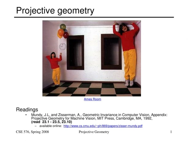
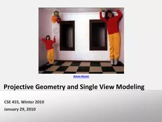
Ames Room Projective Geometry and Single View Modeling CSE 455, Winter 2010 January 29, 2010
Announcements • Project 1a grades out • https://catalysttools.washington.edu/gradebook/iansimon/17677 • Statistics • Mean 82.24 • Median 86 • Std. Dev. 17.88
Project 1a Common Errors • Assuming odd size filters • Assuming square filters • Cross correlation vs. Convolution • Not normalizing the Gaussian filter • Resizing only works for shrinking not enlarging • Convolution operation is a cross-correlation where the filter is flipped both horizontally and vertically before being applied to the image:
Image rectification p’ p • To unwarp (rectify) an image • solve for homography H given p and p’ • solve equations of the form: wp’ = Hp • linear in unknowns: w and coefficients of H • H is defined up to an arbitrary scale factor • how many points are necessary to solve for H?
2n × 9 9 2n Solving for homographies A h 0 Defines a least squares problem: • Since h is only defined up to scale, solve for unit vector ĥ • Solution: ĥ = eigenvector of ATA with smallest eigenvalue • Works with 4 or more points
(x,y,1) image plane The projective plane • Why do we need homogeneous coordinates? • represent points at infinity, homographies, perspective projection, multi-view relationships • What is the geometric intuition? • a point in the image is a ray in projective space -y (sx,sy,s) (0,0,0) x -z • Each point(x,y) on the plane is represented by a ray(sx,sy,s) • all points on the ray are equivalent: (x, y, 1) (sx, sy, s)
A line is a plane of rays through origin • all rays (x,y,z) satisfying: ax + by + cz = 0 l p • A line is also represented as a homogeneous 3-vector l Projective lines • What does a line in the image correspond to in projective space?
vanishing point v Vanishing points image plane camera center C line on ground plane • Vanishing point • projection of a point at infinity
line on ground plane Vanishing points • Properties • Any two parallel lines have the same vanishing point v • The ray from C through v is parallel to the lines • An image may have more than one vanishing point • in fact every pixel is a potential vanishing point image plane vanishing point v camera center C line on ground plane
Today • Projective Geometry continued
Comparing heights Vanishing Point
Measuring height 5.4 5 Camera height 4 3.3 3 2.8 2 1 What is the height of the camera?
Least squares version • Better to use more than two lines and compute the “closest” point of intersection • See notes by Bob Collins for one good way of doing this: • http://www-2.cs.cmu.edu/~ph/869/www/notes/vanishing.txt Computing vanishing points (from lines) • Intersect p1q1 with p2q2 v q2 q1 p2 p1
Measuring height without a ruler Z C ground plane • Compute Z from image measurements • Need more than vanishing points to do this
The cross ratio • A Projective Invariant • Something that does not change under projective transformations (including perspective projection) The cross-ratio of 4 collinear points P4 P3 P2 P1 • Can permute the point ordering • 4! = 24 different orders (but only 6 distinct values) • This is the fundamental invariant of projective geometry
scene cross ratio t r C image cross ratio b vZ Measuring height T (top of object) R (reference point) H R B (bottom of object) ground plane scene points represented as image points as
Measuring height t v H image cross ratio vz r vanishing line (horizon) t0 vx vy H R b0 b
Measuring height v t1 b0 b1 vz r t0 vanishing line (horizon) t0 vx vy m0 b • What if the point on the ground plane b0 is not known? • Here the guy is standing on the box, height of box is known • Use one side of the box to help find b0 as shown above
Monocular Depth Cues • Stationary Cues: • Perspective • Relative size • Familiar size • Aerial perspective • Occlusion • Peripheral vision • Texture gradient
Camera calibration • Goal: estimate the camera parameters • Version 1: solve for projection matrix • Version 2: solve for camera parameters separately • intrinsics (focal length, principle point, pixel size) • extrinsics (rotation angles, translation) • radial distortion
= = similarly, π v , π v 2 Y 3 Z Vanishing points and projection matrix = vx (X vanishing point) Not So Fast! We only know v’s and o up to a scale factor • Need a bit more work to get these scale factors…
Finding the scale factors… • Let’s assume that the camera is reasonable • Square pixels • Image plane parallel to sensor plane • Principle point in the center of the image
Orthogonal vectors Solving for f Orthogonal vectors
Solving for a, b, and c Norm = 1/a Norm = 1/a • Solve for a, b, c • Divide the first two rows by f, now that it is known • Now just find the norms of the first three columns • Once we know a, b, and c, that also determines R • How about d? • Need a reference point in the scene
Solving for d • Suppose we have one reference height H • E.g., we known that (0, 0, H) gets mapped to (u, v) Finally, we can solve for t
Calibration using a reference object • Place a known object in the scene • identify correspondence between image and scene • compute mapping from scene to image • Issues • must know geometry very accurately • must know 3D->2D correspondence
Chromaglyphs Courtesy of Bruce Culbertson, HP Labs http://www.hpl.hp.com/personal/Bruce_Culbertson/ibr98/chromagl.htm
Estimating the projection matrix • Place a known object in the scene • identify correspondence between image and scene • compute mapping from scene to image
Direct linear calibration • Can solve for mij by linear least squares • use eigenvector trick that we used for homographies
Direct linear calibration • Advantage: • Very simple to formulate and solve • Disadvantages: • Doesn’t tell you the camera parameters • Doesn’t model radial distortion • Hard to impose constraints (e.g., known focal length) • Doesn’t minimize the right error function • For these reasons, nonlinear methods are preferred • Define error function E between projected 3D points and image positions • E is nonlinear function of intrinsics, extrinsics, radial distortion • Minimize E using nonlinear optimization techniques • e.g., variants of Newton’s method (e.g., Levenberg Marquart)
Alternative: multi-plane calibration Images courtesy Jean-Yves Bouguet, Intel Corp. • Advantage • Only requires a plane • Don’t have to know positions/orientations • Good code available online! • Intel’s OpenCV library:http://www.intel.com/research/mrl/research/opencv/ • Matlab version by Jean-Yves Bouget: http://www.vision.caltech.edu/bouguetj/calib_doc/index.html • Zhengyou Zhang’s web site: http://research.microsoft.com/~zhang/Calib/
Some Related Techniques • Image-Based Modeling and Photo Editing • Mok et al., SIGGRAPH 2001 • http://graphics.csail.mit.edu/ibedit/
Some Related Techniques • Single View Modeling of Free-Form Scenes • Zhang et al., CVPR 2001 • http://grail.cs.washington.edu/projects/svm/