Understanding the Action of Projective Camera on Planes and Quadrics
Explore the action of a projective camera on planes and quadrics, including back-projection, apparent contours, transformations, and camera rotation. Learn about the significance of camera centers, zooming, and camera rotations in geometric transformations. Discover practical applications and synthetic view generation techniques.

Understanding the Action of Projective Camera on Planes and Quadrics
E N D
Presentation Transcript
Action of projective camera on planes Choose the world coordinate frome so that X-Y plane corresponds to a plane π in the scene such that points In the scene plane have zero Z coordinate. The map between the point on plane π and its image is a general planar homography: x = H xπ ; H is 3x3 The most general transformation that can occur between a scene plane and an image plane under perspective imaging is a plane projective transformation
Action of projective camera on lines forward projection A line in 3D space projects to a line in the image. Suppose A and B are points in space with their projections being a, and b under P; Then a point on a line that joins A and B i.e. X(μ) = A + μ B Is the point: Which is on the line joining a and b. Set of points in space mapping to line l via the camera matrix P is plane PT l Line and camera center define a plane; image of the line is the intersection of this plane with image plane. back-projection
Action of projective camera on conics Conic C backprojects to a cone back-projection to cone
Images of smooth surfaces Image outline of a smooth surface results from surface points at which the imaging rays are tangent to the surface • The contour generator G is the set of points X on S at which rays are tangent to the surface. The corresponding apparent contour g is the set of points x which are the image of X, i.e. g is the image of G • The contour generator G depends only on position of projection center and not on image plane; g depends also on rest of P • For parallel projection with direction k: all rays parallel to k which are tangent to surface S, form a “cylinder” of tangent rays; • Curve along which the “cylinder” meets the image plane is the apparent contour; Both the contour generator and apparent contour depend on k. • The apparent contour γ is also called “outline or Profile”.
Action of projective camera on quadrics back-projection to cone Under camera matrix P, the apparent contour of a Quadric Q is the conic C given by: Outline curve of a quadric are all points where backprojected rays are tangent to the quadric surface Summary: apparent contour of a quadric is a conic. The contour generator is also a conic The plane of G for a quadric Q and camera center C is given by P=QC
The importance of the camera center • Object in 3 space and camera center define “set of rays” • An image is obtained by intersecting these rays with a plane • Images obtained with the same camera center may be mapped to one another by a plane projective transformation • Assume two cameras • Same camera center • This is the 3x3 planar • Homography relating x and x’
Moving the image plane (zooming) Changing the focal length, can be approximated as displacement of image plane along principal axis x and x’ are images of a point X before and after zooming respectively x’ = H x where Assume only focal length Is different between K and K’ Conclusion: the effect of zooming by a factor of k is to multiply the Calibration matrix K on the right by diag(k,k,1)
Camera rotation • Pure rotation about camera center. • x and x’ image of a point X before and after rotation. • x’= H x where: H is called conjugate rotation: same eigen values, up to a scale factor, μ, of the rotation Matrix: ; So, phase of complex eigenvalues of H can be used to find rotation. Can also be shown that the eigenvector of H corresponding to the real eignenvalue is the vanishing point of the rotation axis click on 4 sets of correspondence between A and B to determine H; theta = 4.66 degrees. vanishing point of rotation axis is (0,1,0)T , i.e. virtually at infinity in the y direction; so rotation axis is parallel to y direction B A C
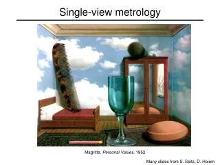
Application: generate synthetic view • In fronto parallel view (1): a rectangle is imaged as a rectangle; (2) world and image rectangle have same aspect ratio. • Approach: synthesize fronto parallel view by warping an image with the homography that maps a rectangle imaged as a quadrilateral to a rectangle with the correct aspect ratio. • Compute the homography H that warps the image quadrilateral to a rectangle with the known aspect ratio • Projectively warp the source image with this homography
close-up: interlacing can be important problem!
Planar homography mosaicing more examples
Projective (reduced) notation Can be shown that if canonical projective coordinates are chosen for world and image points, i.e. Then, camera matrix Satisfies xi = Pxi which means that the camera center is given by This form of P is known as reduced camera matrix; Completely specified by the 3 degrees of freedom of camera center C Shows that all images acquired by cameras with the same camera center are projectively equivalent Camera has been reduced to its essence: a projective device whose action is to map P3 to P2 with only the position of the camera center affecting the results.
Moving the camera center If C is fixed, but camera rotates or zooms, transformation of image only depends on the image plane motion NOT on 3D space structure If C moves, map between images depends on 3 space structure it is looking at: Important special case of 3-space structure: all scene points are co-planar: 2 images with motion parallax (camera center moving) are still related by planar homography motion parallax epipolar line
What does calibration give? Image point x backprojects to a ray defined by x and camera center calibration relates image point to the ray’s direction Points on a ray X = λ d with d being a direction, map to a point on the image plane x given by: Get d from x by : Angle between two rays with directions d1 and d2 corresponding to x1 and x2 if K is known, can measure angle between rays from their image points. A camera for which K is known is called calibrated; A calibrated camera is a direction sensor able to measure the direction of rays like a 2D protractor θ An image line l defines a plane through the camera center with normal n=KTl measured in the camera’s Euclidean frame
The image of the absolute conic Image of the points on the plane at infinity i.e. X∞ = ( d T , 0)T is given by: independent of camera center mapping between p∞ to an image is given by the planar homogaphy x=Hd, with H=KR Absolute conic lies on p∞ . image of the absolute conic (IAC) • IAC depends only on intrinsics, not on camera orientation or position • angle between two rays: independent of projective coordinate frame of image • if x1 and x2 are image points corresponding to orthogonal direction then • Dual image of absolute Conic: DIAC=w*=KKT • w K: once ω is known, can find K via cheloski factorization • image of circular points are on ω ω w
A simple calibration device to find K • compute H for each square ; H maps corners (0,0),(1,0),(0,1),(1,1) to their image points • alignment of the plane coordinate system with the square is a similarity transform and does not affect the position of circular points • compute the imaged circular points: H(1,±i,0)T = h1 ±i h2 if H = [ h1 h2 h3 ] • image of circular points are on ω. • fit a conic to 6 imaged circular points: If h1 ±i h2 lies on ω then (h1 ±i h2)Tω (h1 ±i h2 ) = 0 • set the real part and the imaginary part to zero: two linear constraints in ω need 3 planes • Real h1Tω h2 = 0 ; Imaginary: h1Tω h1 = h2Tω h2 linear in ω • compute K from w through cholesky factorization (= Zhang’s calibration method)